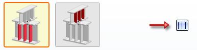
"Civil Engineering functions" docking window > Steel Engineering > General > Purlin joint (3206)
With this design variant, you bolt together a purlin and a girder with a maximum of 4 bolts. For reinforcement, up to 3 stiffeners can be installed on the purlin and the girder.
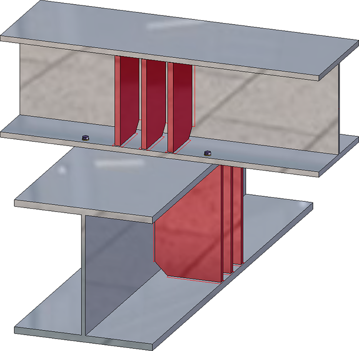
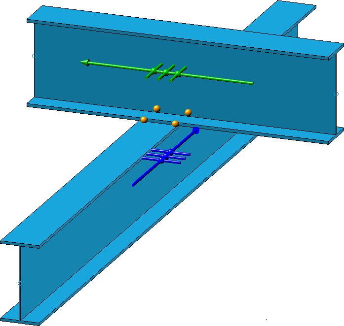
During input, the current settings are visualised in your drawing: insertion direction, stiffeners and boltings.
By clicking on the Preview button, you can display an exact preview of the purlin joint - based on the currently entered data. If you want to correct the data, make the changes and click Preview again to update the preview. Click OK to install the purlin joint with the current data and close the dialogue window. If you exit the dialogue window with Cancel, the function is cancelled without insertion or without changing the connection.
The settings of the dialogue window can be saved as favourites and reused at any time. To do this, click on the  symbol at the bottom left of the dialogue window to activate the context menu. You can find more information on the administration of favourites in the Manage Favourites topic of the HiCAD Basics Help.

Configure purlin joint
The purlin joint is configured via the settings on the various tabs of the dialogue window.
Beams+Profiles
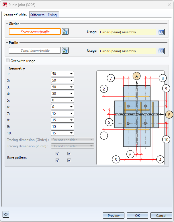
On this tab you select the girder and the purlin and you define the dimensions of the purlin joint.
Specify the girder and the purlin in your drawing. Click on the  symbol to change the selection.
In the Usage field, you can define which usage is to be assigned to the girder or purlin assembly. If a usage is already assigned to the assembly, the checkbox Overwrite usage can be used to specify whether this usage should be retained or replaced by the usage selected here.
Determine the dimensions.
A maximum of two rows of holes on girder and purlin are possible. Select the desired number of rows of holes by activating the corresponding checkboxes.
If the tracing dimensions of the purlin or the girder (for profile irons the distance of the rivet rows in web or flange from certain edges of the cross-section) are to be taken into account in the rows of holes, then select this in the respective list box.
 How the distance between the stiffeners is taken into account depends on the settings on the Stiffeners tab.
Stiffeners
Up to 3 stiffeners can be installed on both the purlin and the girder. Click on the corresponding button to switch between the settings for the stiffeners on the girder and on the purlin (1). In the line (2) below, you can then define the settings for three stiffeners each.
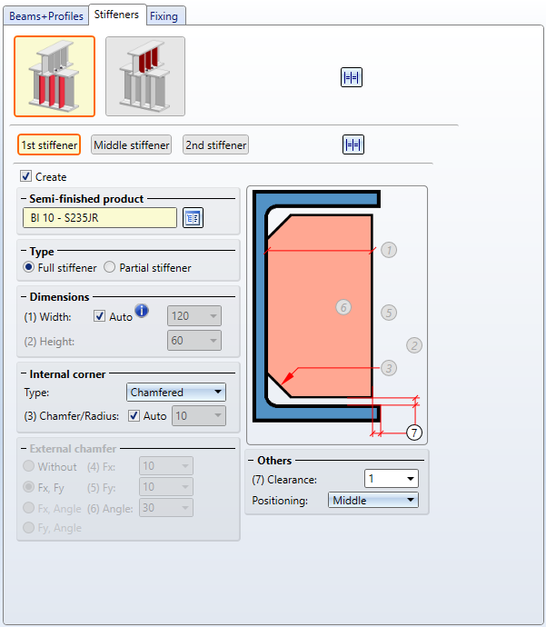
Specify the semi-finished product, type and dimensions as well as the Internal corner type of the three stiffeners. If you do not want a stiffener to be created, deactivate the Create checkbox.
For each stiffener, you can also specify in the field Positioning which edge should be relevant for insertion: The Middle, the Front side or the Back side. The distances (1) - (4) specified on the Beams+Profiles tab is then used for the setting selected here.
An example:
You install three stiffeners and select centre, back, front. On the Beams+Profiles tab you have chosen a distance of 75. The stiffeners are then installed so that the back of the second stiffener is the specified distance from the centre of the first stiffener and the front of the third stiffener is the specified distance from the back of the second stiffener.
If you want to use the settings of the current stiffener for all three stiffeners, click on  .
.

If you want to use the current settings for the stiffeners for both the girder and the purlin, click on .
The stiffeners will be assigned to the respective profile.
Fixing
The stiffeners are mounted to the girder by bolting.
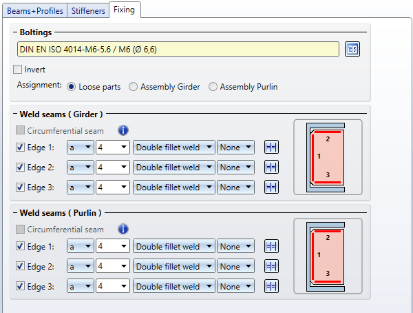
The bolt and hole can be selected the standard parts catalogue by clicking on the  symbol.If the direction of the bolting is to be inverted, activate the checkbox Invert.
The parts of the bolting can be combined separately in a structure assembly with the name Loose parts or assigned to the assembly of the girders or the purlin.
The stiffeners are welded to the purlin or the girder. By activating the corresponding checkboxes, you determine here which welds are to be created between the beam and the stiffeners:
- a circumferential seam or
- weld seams on specific edges.
For each edge you can select the type of thickness designation, the weld seam thickness, the weld seam type and the inspection category. If you want to use the same settings for the other edges, click on the Equate icon.

Connections + Variants (3-D SE) • Dialogue Window for Connections (3-D SE) • The Catalogue System for Connections+Variants (3-D SE)