Function call and dialogue window
Steel Engineering > New > Beam 
With this function, 3-D standard beams and profiles, multi-part standard beams, prototype beams and elongated plates can now be inserted. The selection is made in the following catalogues:
- Semi-finished products > Plates,
- Semi-finished products > Cold rolled sections,
- Semi-finished products > Beams + Profiles,
- Factory standards > Multi-part standard beams and
- Factory standards > Prototype beams.
The insertion of the beams and profiles takes places via the dialogue window shown below.
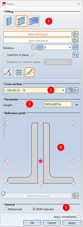
There you select the desired cross section and enter the required parameters such as the Length of the beam or profile, the angle of rotation or the direction. Which parameters have to be specified explicitly depends on the selected fitting type and the selected cross section.
The dialogue window consists of the following areas:
|
Insert beam or profile in the drawing |
|
|---|---|
|
Apply immediately |
If this checkbox is active, the beam is immediately adopted after entering the parameters required for the selected installation type. Corrections, e.g. changing the length or the angle of rotation, are then no longer possible for this beam in the dialogue. The dialogue window remains open so that you can directly insert further beams. |
|
OK |
The beam is inserted as shown in the preview and the dialogue window is closed. |
|
Apply |
The beam is inserted. In contrast to OK, the dialogue window remains open so that you can insert further beams directly.. |
|
Cancel |
The function is terminated without inserting the beam. |
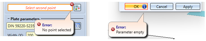
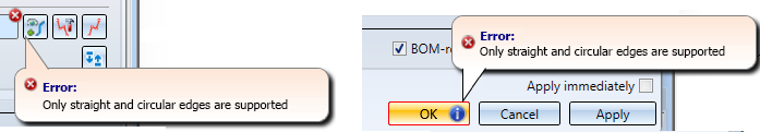
Incorrect or missing entries are indicated in the dialogue with the  symbol at the input field , and the
  symbol at the OK button. If you move the cursor over the symbol, a corresponding message is displayed, e.g.
![]() Please note:
Please note:
- As soon as you have entered the required parameters, a preview of the beam is displayed. You can change the parameters as long as you have not yet accepted the beam displayed in the preview.
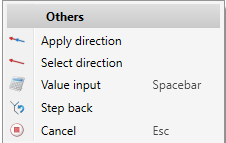
- If you right-click in a value input field, a context menu opens with whose functions you can, among other things, transfer angles and lengths from existing drawing objects into the input field.
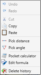
For example, you can use the Pick distance function to transfer a beam length from the drawing. Or you want to take over the angle of rotation for the beam from the drawing, then use the function Pick angle.
Please also read the general notes on Elongated Plates and Multi-Part Standard Beams in the same-named topics.

Fitting, Cross section and Parameters
In the Cross section area, select the desired beam type. To do this, click on the symbol and then select the desired beam in the catalogue.
Alternatively, you can also select a beam that already exists in the drawing as a reference beam. To do this, click on the  symbol and then select the reference beam.
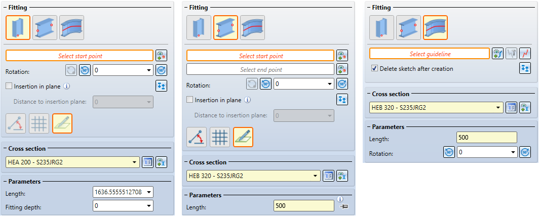
The following types of Fitting are available for inserting a beam:
 Insertion perpendicular to processing plane
The actions and parameters required for fitting depend on the type of fitting that was selected.
|
Actions / Parameters |
Fitting |
||||||
|---|---|---|---|---|---|---|---|
|
|
|
|
|||||
|
Select start point After selecting the point, Point is displayed in the dialogue window. If you want to change the start point, click on the |
|
|
|
||||
|
Select end point see start point |
|
|
|
||||
|
Select guideline Here you select a planar sketch or a 3-D sketch as guideline. The beam is installed along this guideline. |
|
|
|
||||
|
Rotation The beam is rotated around the beam axis by the specified angle .
|
|
|
|
||||
|
|
|
|
||||
|
Switch ends Click on the symbol to mirror the beam to be inserted (useful e.g. for L-beams). |
|
|
|
||||
|
Insertion in plane If this checkbox is active, all selected points are projected into the current working plane. The beam is then inserted in such a way that the projection of the start point from the selected reference point of the beam has the specified distance to the insertion plane. |
|
|
|
||||
|
Length |
|
|
|
||||
|
Width of elongated plate only if an elongated plate from the catalogue Semi-finished products > Plates > Plate is selected as the cross-section. |
|
|
|
||||
|
Fitting depth The fitting depth is the distance from the starting point of the beam to the selected starting point. The actual beam length is then the sum of the length and fitting depth. |
|
|
|
||||


Insertion perpendicular to processing plane
The insertion takes place perpendicular to the current processing plane in the Z-direction. If no processing plane is available, the XY-plane of the world coordinate system is used.
- Select the start point.
- If the beam is to be rotated around the beam axis, enter the angle or select one of the rotation functions
 or .
or . .
. - If the start and end points are to be switched, click on the
 . symbol.
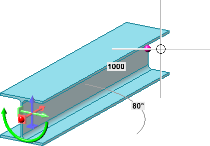
 - Enter the Length of the beam and - if desired - the Fitting depth. The actual beam length is then the sum of Length and Fitting depth.
- If the checkbox Insertion in plane is active, the start point is projected into the current processing plane and the beam is inserted perpendicular to this point - taking into account the value entered for Distance to insertion plane.
- As long as you have not yet adopted the beam, you can rotate it dynamically with the cursor by clicking on
 .
.
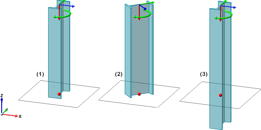
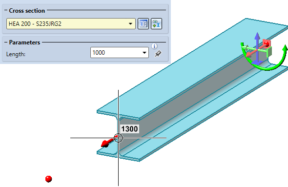
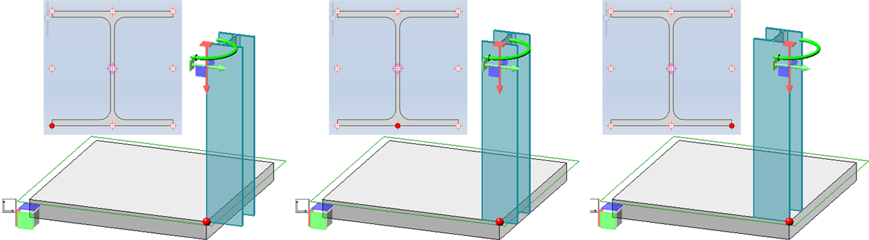
(1) Length only, (2) Length and Angle 45°, (3) Length + Fitting depth
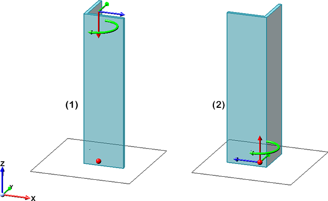
(1) Insertion of an L-profile, (2) Insertion with switching of start and end point
Insertion via 2 points 
Here the insertion is done by selecting two points. The position of the beam is defined by the start point. The end point determines length and direction.
- Select the start point. HiCAD displays a plane preview at the start point, which represents the current coordinate system. The drawing plane is parallel to the processing plane active when the function is called or to the XY-plane of the world coordinate system and runs through the start point. As with the sketching technique, you can now determine the end point as follows:
|
|
Angle + Distance In this mode (default setting), the angle and the distance to the start point are displayed at the cursor. To determine the end point, place the cursor at the desired position and drop it with a left-click.
The values for the distance and angle grid can be preset in the Configuration Editor at System settings > Identification in the Grid section. |
|
|
XY-grid The X- and Y- distance to the start point are displayed. To determine the end point, place the cursor at the desired position and drop it with a left-click. |
|
|
Free In this mode you can draw freely, i.e. without a grid. The X- and Y-distances to the start point are displayed on the cursor. To determine the next point, place the cursor at the desired position and drop it with a left-click.
|


 Points determined in this mode always lie in the current processing plane.
To determine the length and direction of the beam, there are three possibilities.
- Identify the end point with the cursor.
- Take over the length and direction of the last beam with a right-click. The prerequisite is that you have not left the function in the meantime.
- Determine the end point with another point option, e.g. Relative R.
By default, the length is determined by the distance between the two points. A special feature here, however, is the possibility to switch the type of length determination. The buttons  or
or  are available for this purpose.
|
|
With this setting, the length is automatically determined by the distance between the start and end points. The Length field is then greyed out. This is the default setting. |
|
|
If this setting is active, the end point only determines the direction of the beam. The beam length is determined by the value entered in the Length field. In addition, the direction is shown in the drawing by an arrow. By dragging this arrow with the cursor, the length can also be changed.
|
If the checkbox Insertion in plane is active, the beam is installed in such a way that the selected reference point has the specified distance to the insertion plane. The beam axis runs parallel to the plane.
Insertion along guideline 
Here you insert beams along a guideline. This can be a planar sketch or a 3-D sketch. The beams of the selected type will be placed on the lines of the sketch. The individual beams are mitred or curved depending on the sketch.
Select the desired guideline in the drawing.
The following options are also available for selection:
|
|
Select guideline Click on the symbol to select another sketch as the guideline. |
|
|
Process sketch With this function you can process a previously selected sketch. For this purpose the Process sketch dialogue window is displayed. Modify the sketch as desired and then click Apply sketch in the dialogue window. The dialogue will continue with the modified sketch |
|
|
New sketch in plane With this function you can create a new sketch. Draw the desired sketch and then click Apply sketch. The dialogue continues with the new sketch. |


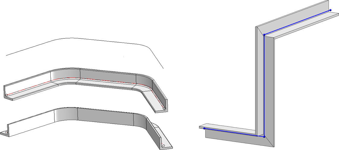
In the following image, an L-beam on a plane sketch is shown on the left, once without and once with the ends switched. On the right, an L-beam has been placed on a 3-D sketch.
- The selected guideline may only consist of straight and circular lines, other elements such as ellipses or B-spline edges are not allowed. The lines of the sketch must not intersect or lie on top of each other and no more than 2 lines may converge in one point. If the sketch selected as a guideline does not meet the necessary requirements, this is indicated by the symbol at the input fileld(s) and by the symbol at the OK button, e.g.
- Not all beam processing functions can be applied to beams that are inserted along guidelines.
-
For beams that are installed along a composite edge, the following must be taken into account for the functions Change length and Change beam length, via new total length: If there is an circular arc at the beam end of the composite edge to be extended, the value of the extension or the total length is the arc length of the extension. For straight beam ends, it is the value of the straight extension. This means that along a composite edge it is also possible to extend it directly without having to load the guideline (in the Feature), extend it and then replace it.
Reference point
The reference point determines the orientation of the beam in the coordinate system and is also taken into account when exchanging beams.
The centre of gravity (e) of the beam cross-section is preset. If you want to use another of the predefined reference points, simply click on the corresponding point symbol in the dialogue window.
|
|
a Top left, b Top axis, c Top right d Axis left, e Centre of gravity, f Axis right g Bottom left, h Bottom axis, i Bottom right |
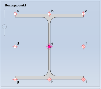
The left slider can be used to zoom the reference point display of the dialogue window.
The following image shows the alignment with different reference points. The red point in the preview is the start point.
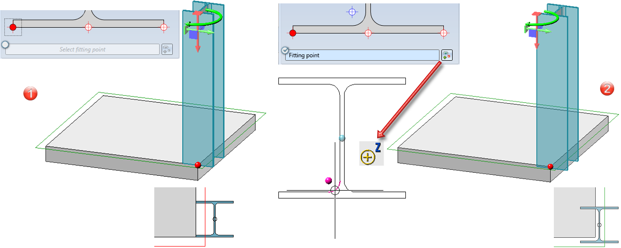
You can also select a fitting point as an insertion aid. However, this is not possible if beams are placed along a sketch.
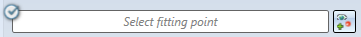
To do this, activate the option and then click on the  symbol. HiCAD displays a preview of the beam cross-section. Then select the desired fitting point. This point is then the insertion point of the beam. This does not change the selected reference point. If the option is activated and no fitting point is determined, the centre of gravity of the beam is used as the insertion point.
In the image below the insertion without fitting point is shown on the left. On the right, the centre of the lower left fillet has been selected as the fitting point.
General
In this area you can determine by activating/deactivating the corresponding checkboxes
- whether the part should be referenced and
- whether the part should be BOM-relevant.
