General information
Civil Engineering functions docking window > Steel Engineering >Stairs + Railings > Railing > Railing Configurator (Railings along beams)
The Railing Configurator, which is part of the HiCAD Steel Engineering module, enables you to configure and insert individual railings along beams, e.g. for staircases created with the Staircase Configurator, or various platforms.
Before using the Railing Configurator, please read the information given in the Railing Configurator - Important Notes topic.
As this function is rather complex, the settings will initially be explained by means of a simple staircase example. How to proceed for multi-storey stairs and railings with equidistant railing posts is explained in a separate example.
First, a railing is to be added to the staircase that has been generated with the Railing Configurator (Stringers: U280 beams). Please note that in this example, the ISD default settings are used.
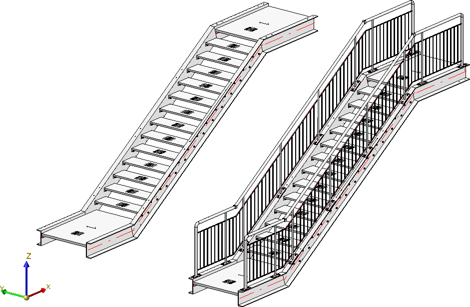
Simple staircase with railing
Before starting the Railing Configurator, please make sure that the coordinate system is aligned correctly. The Railing Configurator aligns the railings to the Z-axis. If you are not sure, select Drawing > Others > World CS  to activate the 3-D World CS (=default CS).
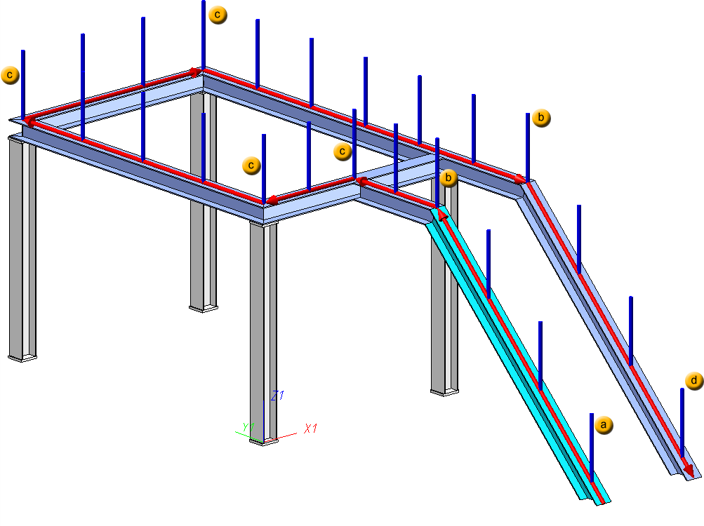
After calling the Railing Configurator you will be prompted to identify, one by one, the Steel Engineering beams onto which the railing is to be placed. The "path" that is formed by the beams will define a virtual composite edge that will serve as a guideline for the route of the railing. Posts, handrail, infill and knee rails will then be located on a composite edge running parallel to this guideline, the so-called walking line.
When selecting the beams, please note that the selection point for the first beam is the start point according to which the subsequent division of the railing is based (fixed distance with rest at the beginning or end). For example, in practice, designers follow the walking direction from bottom to top when designing stair railings. The selection point for the next beam determines the direction in which the railing is installed. If the order of the selected beams results in only one possible walking direction of the railing, the selection of the end of a beam is ignored
In the example shown below, the first beam is selected at point (1), the second beam at point (2). A shows the result before HiCAD 2022 SP1, B the result in HiCAD 2022 SP1.
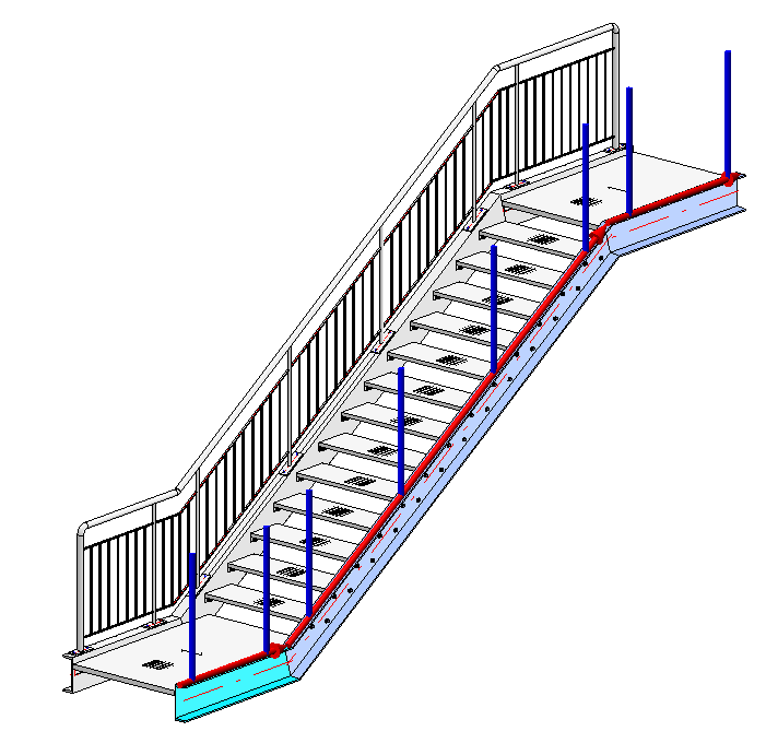
During selection of the beams, the walking line and walking direction will be visualized by means of a red arrow. This walking line determines the height and the fixing position of the railing. The distribution of posts, too, will be visualized according to the last selected settings. As soon as you change the settings in the dialogue window, the preview will be updated.
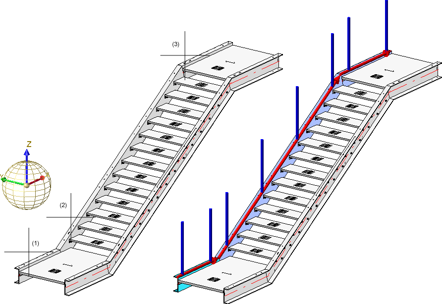
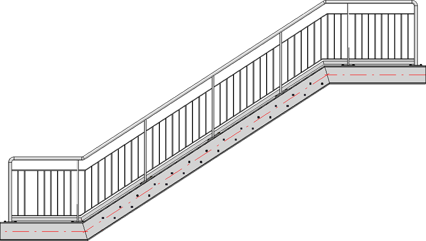
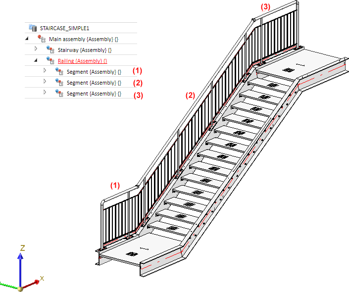
 Example, Step 1 - Selection of beams (1), (2) and (3) -> Walking line and direction will be visualized
You end the selection of beams by clicking the middle mouse button. This automatically opens the Railing Configurator dialogue window.
This dialogue window consists of the following tabs:
General parameters and component selection:
Parameters for the definition of the railing components:
The settings can be saved as Favourites and reused at any time. At the bottom left of the dialogue window, click the  symbol to activate a menu with Favourites functions. More information about Favourites can be found in the Manage Favourites topic of the HiCAD Basics Help.
While the window is open, you can display a Preview of the railing generated with the current settings by clicking the same-named button. You can use the zoom functions to enlarge or downsize the object on the screen.
Click OK to start the generation of the railing. The progress of the generation will be indicated in a progress bar.
 Please note:
- All settings specified in the Railing Configurator dialogue window will be saved as defaults and will be shown when you call the Configurator again.
- An assembly called Railing will be created for the railing. This assembly in turn consists of sub-assemblies called Segment, which contain the railing elements on the individual beams.
If there are several beams in succession that are aligned in the same direction, the railing elements of these beams will be combined into one segment assembly. As a result, continuous hand rails and knee rails will be formed on these beams. The updating and modification of existing railings (before V 2016 SP2) witch such areas will still be performed using individual segment assemblies and thus with non-continuous hand rails and knee rails.This also applies to curved beams with equal radius and mid point from HiCAD 2019 2019 SP2, Patch 1 onwards. The updating and modification of existing railings (before Version 2019 SP2, Patch 1) will still be performed with separate segment assemblies and thus with non-continuous hand rails and knee rails.
- A feature log entry called Railing along beams will be entered in the feature log.
- Various components and connections belong to a railing, which are all created via Design Variants. The ISD has supplied the corresponding Design Variants for this purpose. If desired, you can also create customized Design Variants for the components. If you have any questions about the procedure, contact our Consulting team.
- To select the variant for a component, just click on the corresponding tab. Select the desired variant from the listbox, click the
 icon to directly choose the component from the HiCAD catalogue and specify all required settings.
 - In some tabs you can use
 and
and  symbols to open and close input areas.
 - The updating of stairs and railings with deleted parts has no longer been possible since HiCAD 2017. However, this only concerns the stairs and railings that have been created with HiCAD 2017 (Version 2200) or newer.
- Railings created with older versions of the Railing Generator (from Version 2101.0 onwards) can be updated or changed if you have subsequently deleted parts that were created by the corresponding variant. However, these deleted parts will be re-created upon updating if these are required due to the parameters and the geometrical situation.
- You can also create curved railings in one plane. However, this is not possible for beams that were placed along composite edges.
Curved railing, created along a curved beam

General parameters and railing component selection
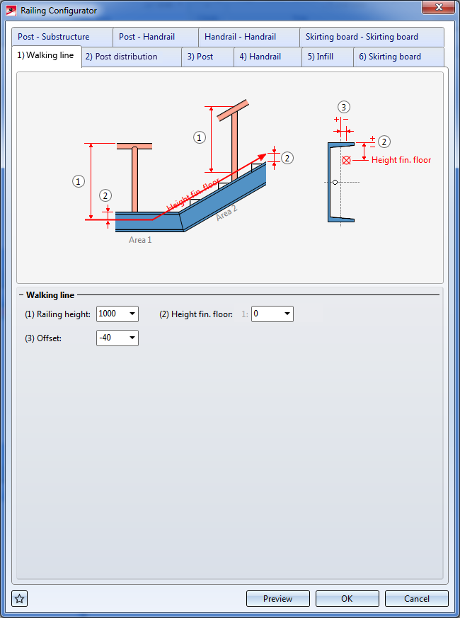
1) Walking line
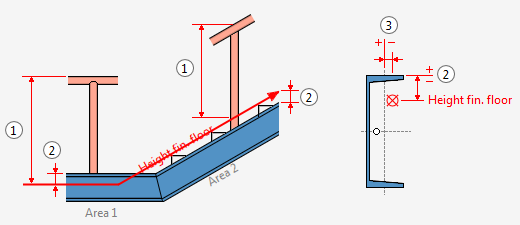
Railing height (1)
This value determines the railing height from the finished floor. This height always refers to the top step corner.
Height fin. floor (2)
This value determines the distance between the upper beam side and the finished floor. If you enter a value greater than 0 or less that 0, the entire walking line will be moved upwards or downwards. Depending on the type of the selected beams you can also specify different heights for the finished floor. For this purpose, the selected beams are subdivided into areas. The first beam belongs to area 1. HiCAD will then check whether the next beam is located in the same plane. If this is the case, it also belongs to area 1. If not, area 2 starts with this beam etc. For each of these areas the value Height fin. floor can be specified separately.
Offset (3)
Here you specify the lateral distance to the beam axes - seen in positive direction to the left / negative direction to the right in walking direction (3). Please note that you can also take the values directly from the drawing by right-clicking the input field and selecting Pick distance.
2) Post distribution
On this tab you specify which posts are to be created, and how the posts are to be distributed along the walking line. The post distribution can take place automatically or manually.
One distinguishes between start post, end post and transition post.
Automatic post distribution
Reference for post distribution
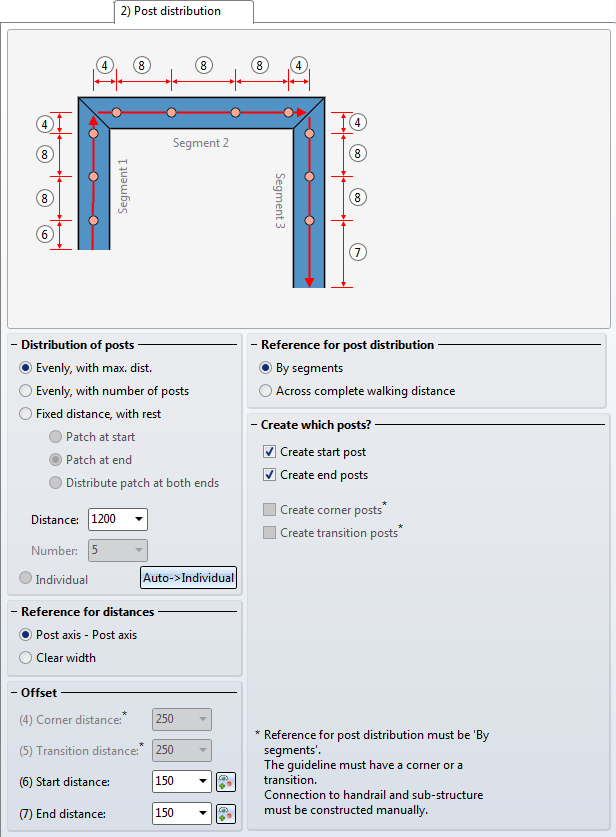
The distribution of the posts can take place by segments or across the complete walking distance. A segment is the length between the virtual axes, i.e. the perpendiculars in the corner points or inflexion points of the red walking line.
The By segments setting makes sense for the creation of balcony railings. Here, the posts will be evenly distributed to the corners, and the corner fields are also filled evenly .
On the other hand, the Across complete walking distance setting can be useful for the creation on railings on staircases, e.g. for multi-storey staircases and railings with equal post distances.
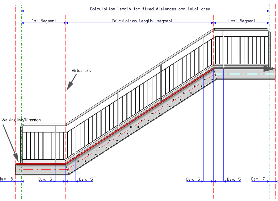
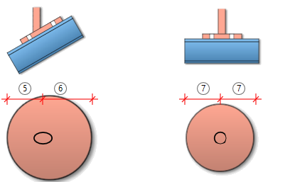
A segment is the length between the virtual axes (i.e. the perpendiculars in the inflexion points of the red line, pls. see image below), e.g.:
- First segment: From the start of the red line, offset by Dimension 6 to the first axis (First inflexion point)
- Last segment: From the end of the red line, offset by Dimension 7 to the last inflexion point of the red line
- In the stair flight segment, HiCAD calculates the post distances according to the corresponding, specified options (equal post distances or evenly with number of posts), i.e. the "virtual axis" of the red lines - 2x Dimension 5.
- The post distances of Dimension 5 are considered here.
Distribution of posts
- Evenly, with max. distance
If you select this option, the Start distance (Dimension 6) and the End distance (Dimension 7) will be subtracted from the total length of the walking line. The rest will be distributed in such a way that the distances between the posts will be equal and will not exceed the specified maximum distance. The Transition distance (Dimension 5) will not be considered.
- Evenly, with number of posts
Here, the calculation length will be divided by the number of posts, with regard to the axis length. The value in the Distance field as well as the Transition distance (Dimension 5) will not be considered.
- Fixed distance, with rest
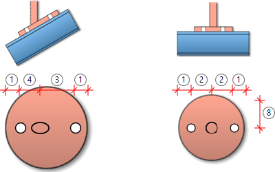
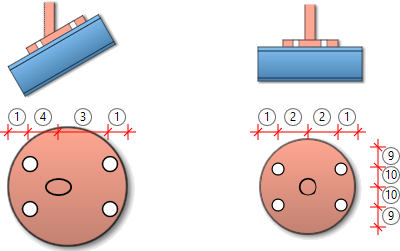
If you select this option, you need to check whether the remaining rests (patches) are to be located at the start, at the end or on both sides. It is therefore recommended to use "virtual" vertical auxiliary lines during the construction process. For if the railing posts are to be located below one another after completion of the construction, this can be achieved easiest with this option. This means that the specified dimensions will only be used for the active flight of stairs (walking line). In the sketch you can see that the flight of stairs 1 places Dimension 6 at the bottom right (at the start), and Dimension 7 at the left. When you activate the flight of stairs 2, Dimension 6 will be located on the left, and Dimension 7 on the right. This should be taken into account to ensure that the correct distances will be entered. Dimension 5 will not be considered.
When selecting the beams, please note that HiCAD interprets the first selected beam as the start, which the later partitioning of the railing will be based on (fixed distance with rest at the start or end). In practice, engineers mostly use an upstairs walking direction as an orientation.
For the distribution of posts in the image this means:
- The first post will be offset by Dimension 6 with regard to the first axis
- The second post is located before the first inflexion point of the walking line at the distance of Dimension 5.
- The third post is offset by Dimension 5 with regard to the first inflexion point.
- In the stair flight segment, HiCAD calculates the post distances according to the corresponding, specified options (equal post distances or evenly with number of posts), i.e. the "virtual axis" of the red lines - 2x Dimension 5.
- The last but one post is offset by Dimension 5 with regard to the last inflexion point of the walking line.
- The last post has a distance of Dimension 7 from the end of the walking line.
Example: Distribution of posts by segments
Example: Distribution of posts across complete walking distance (different at transitions)
Reference for distances
The distance can either be interpreted as
- distance between the post axes, or
- as a so-called "clear width" i.e. the inner distance between the posts
Offset
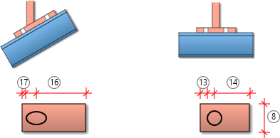
- Corner distance (4)
Distance of the post axes to the corner points of the walking line.
This dimension is only applies if the posts are distributed by segments, and if the Create corner posts beneath Create which posts? has been deactivated.
- Transition distance (5)
The distance of the first post to the beam start
This dimension is only applies if the posts are distributed by segments, and if the Create transition posts beneath Create which posts? has been deactivated. Please note that the mid point of this dimension is always located on a corner point of the walking line.
- Start distance (6)
Distance of the first post to the start of the first beam
- End distance (7)
Distance of the last post to the end of the last beam
If the start point and the end point are not equal, please check which beam you selected first. The start distance always refers to the first selected beam, the end distance to the last selected beam!
The start and end distance, that is, the position of the first and the last post, can also be specified via point determination. To do this, click the  icon and specify the position of the post.
Create which posts ?
Here you specify by activating the corresponding checkboxes which posts are to be created. The creation of corner and transition posts is only possible if the By segments option beneath Reference for post distribution is active and if the guideline has a corner or a transition.
Example, Step 2 - Specify parameters on Walking line (1) and Post distribution (2) tabs
In our example the ISD default settings (with max. post distances, distribution of posts by segments) will be used, with the exception of the Offset value on the Walking line tab. The railing is to be placed in a centred position on the upper beam side. Therefore, select Offset = 0 here.
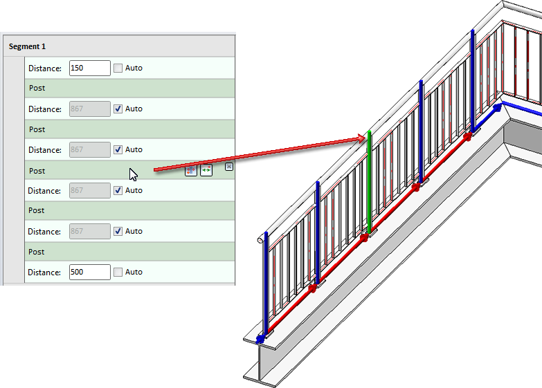
Individual post distribution
The post distribution can also take place manually, i.e. with different distances between the individual posts. For this you can use the  button and the Auto option.
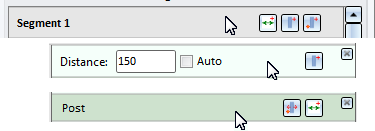
When you click the button, the settings that were last specified on the Post distribution tab of the dialogue window will be displayed as defaults for individual post distribution. This includes the definition of the distances at the start and the end of the walking line, the corner distance and the transition distance with concrete values. Therefore, the Individual option is initially greyed out. The settings can then be modified as described below.
After a click on the button the Individual option will be available. You can then (while the dialogue is open) switch between the other options beneath Distribution of posts and the individual distribution.
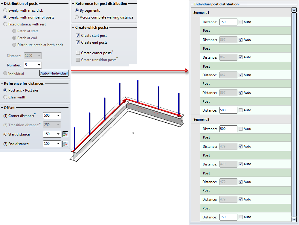
Left: Last settings; Right: Individual post distribution after clicking
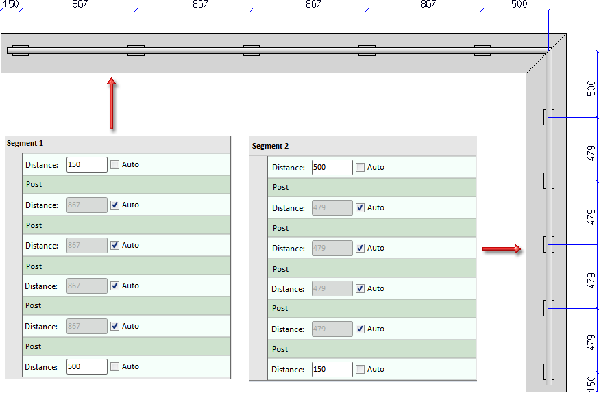
If you activate the Auto checkbox, all distances will be recalculated. If you want to define individual distances, deactivate the corresponding Auto checkbox and enter the required distance. All distances with an active checkbox will continue to be calculated automatically.
When you move the cursor over the entries for the posts, the corresponding post will be highlighted in green in the drawing. Distances between posts are highlighted in red, all other distances in blue.
In the post distribution list you can also add new posts and distances with the help of functions the icons of which become visible when you move the cursor over the Segment, Distance and Post rows.
The meaning of the symbols:
|
Segment |
|
|
|
New distance at start of segment |
|
|
New post at start of segment |
|
|
New post, via point
|
|
Distance |
|
|
|
New post
|
|
|
Delete distance |
|
Post |
|
|
|
Move post, via point |
|
|
New distance Inserts a new auto-distance after the current post. All other distances with active Auto checkbox will be recalculated. |
|
|
Delete post |


The Distance and Post rows can be moved by Drag & Drop.
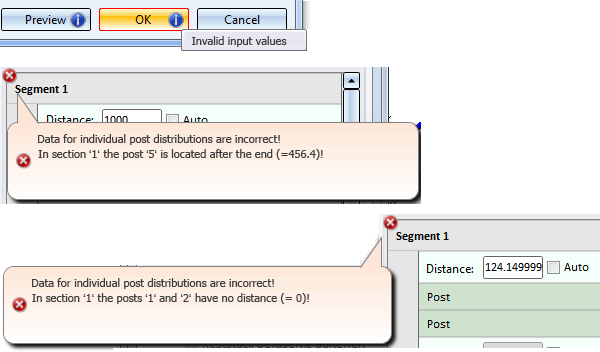
If the post distribution cannot be applied with the specified data, e.g.
- because no distance between 2 posts has been defined, or
- because a post would be located outside the segment due to the entered data,
this will be indicated accordingly on the OK and Preview buttons by the  symbol, and in the post distribution section by the
  symbol. If you move the cursor over the symbols, a short explanation of the error will be displayed, e.g.:
3) Post
One distinguishes between Start posts, Intermediate posts, Corner/Transition posts and End posts.
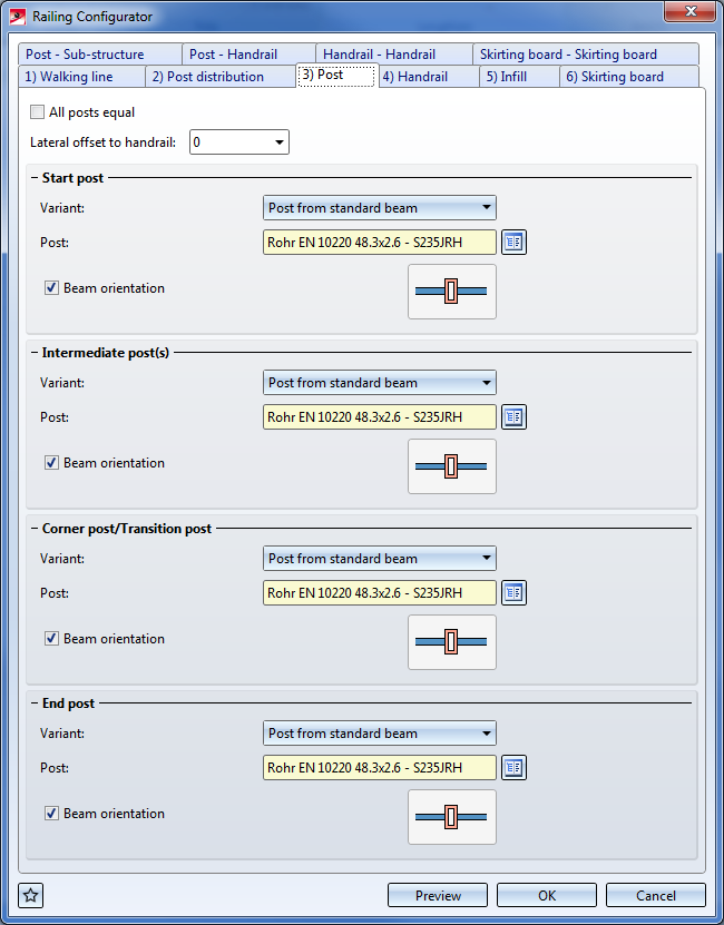
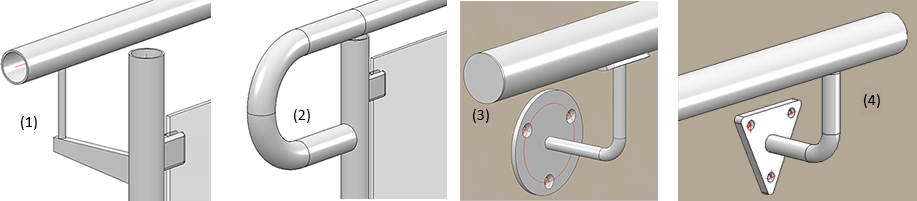
All profiles and factory profiles of the HiCAD Catalogue can be used as posts. You can also use plates, double profiles or sketch profiles as posts.
|
Post from standard beam |
All profiles from the catalogues
|
|
Variant: Steel plate post |
All plates from the catalogues
|
|
Variant: Post of double profiles |
|
|
Variant: Sketch profile |
|
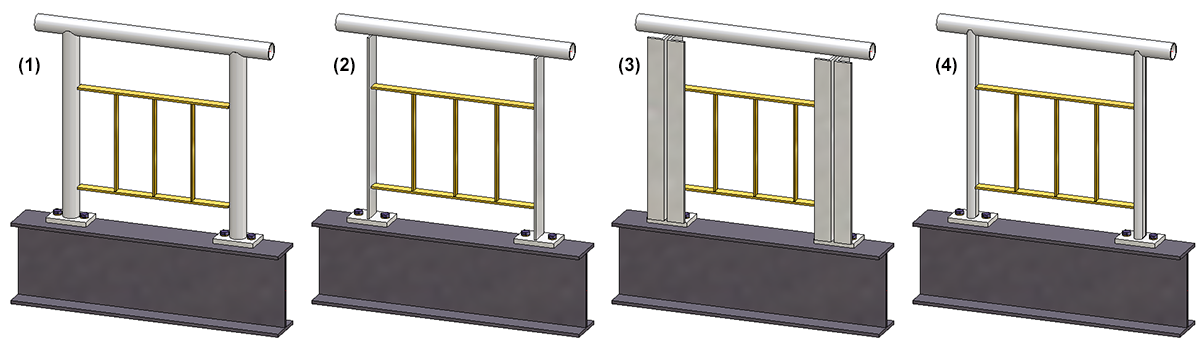
(1) Standard profiles, (2) Plate, (3) Double profiles, (4) Sketch profiles
For all posts you can specify a lateral offset to the handrail. By activating or deactivating the corresponding checkbox, you can also change the Beam orientation.
Please note that specifying an offset currently only makes sense if Variant: Console has been selected on the Post-Handrail tab.
If you want the beam height to be perpendicular the the railing plane, activate the Beam orientation checkbox.
Please note:
Even if you activate the All posts equal checkbox here, the settings on the tabs Post - Substructure and Post - Handrail will not be considered for corner posts and transition posts! The connections on corner posts and transition posts must therefore be reworked manually.
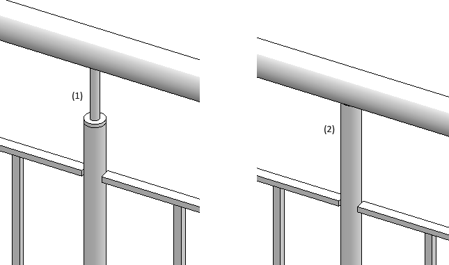
Offset - Example:
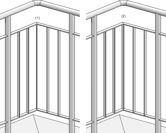
The image below shows the marked handrail and post in top view: (1) without offset; (2) with offset
Please note:
Value inputs in the Corner post/Transition post area will only be possible if the By segments option has been selected beneath Reference for post distribution on the Post distribution tab, and if the guideline has corners or transitions.
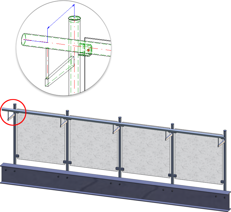
4) Handrail
The variant supplied by the ISD allows an utilization of steel pipes as handrails. In addition, you can specify an excess length for the handrail at the start post and the end post. However, the excess length will only be evaluated if you have selected the variant <do not create>, Trim pipes or Connection with mandrel on the Post - Handrail tab.
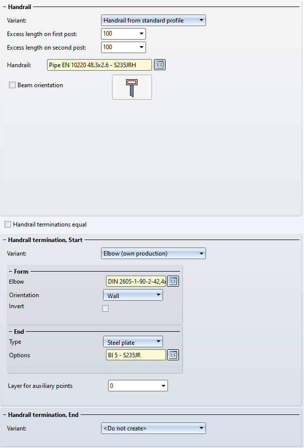
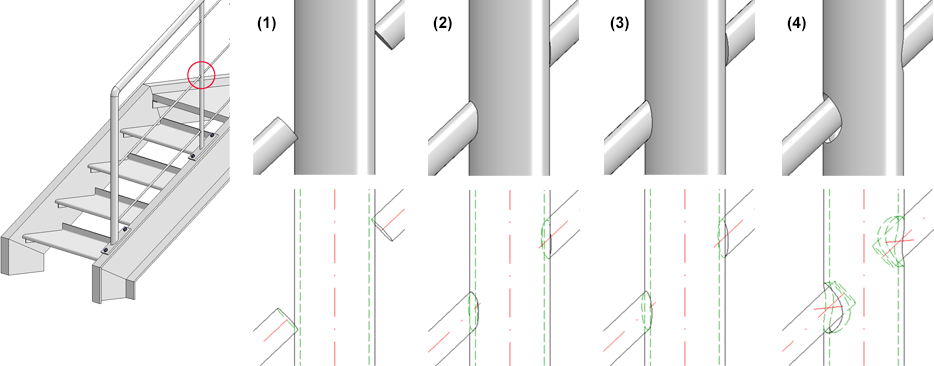
In addition, you have the option here of specifying the termination at the beginning and end of the handrail. Available are end caps and ball caps as well as elbow with or without end cap or steel plate. Elbows can also be oriented towards walls or floors, or reversed by activating the corresponding checkbox.
If the auxiliary points for the selected standard parts are to be assigned to a special layer, enter the number of the layer here. The default setting is Layer 0.
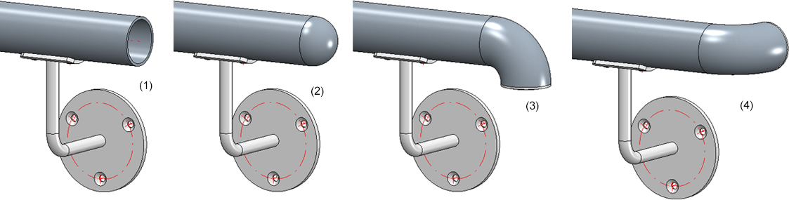
(1) no end element, (2) with ball cap, (3) with elbow and end cap / oriented towards floor, (4) with elbow and end cap / oriented towards wall
5) Infill
You can choose knee rails, glass elements, vertical rods with or without booms, vertical rods with bottom boom, or vertical rods with frame. The infill for corners and transitions (staircase/platform) can be defined separately. However, this is only possible if the guideline has corners and transitions and if the checkboxes for the creation of corner and transition posts have been deactivated on the Post distribution tab.
For corners or transitions, the same infills as specified in the Infill tab will be used by default. If you want to use individual infills here, activate the corresponding checkbox. Please note however that this will only be possible if no corner posts or transitions posts are used.
Knee rails
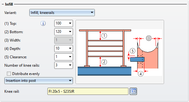
If you want the knee rails to be distributed evenly, activate the Distribute evenly checkbox.
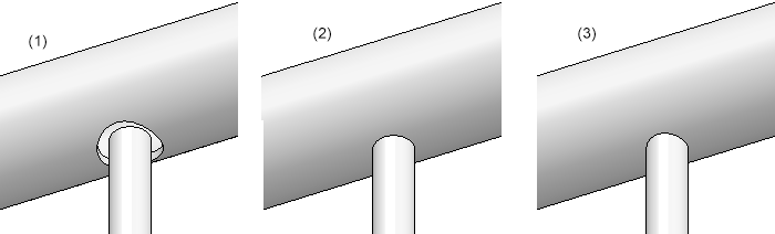
For Knee rails on posts you can choose between the following options:
- Do not trim (1)
- Trim to post (2)
- Trim to front edge of post (3)
corresponds to the function Trim, to outer edge - Insertion into post
Here the infill is inserted into the post, with a definable depth.
Glass elements
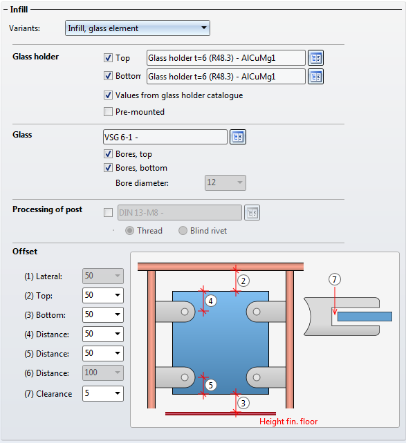
Allowed glass elements (Material and glass structure) are the glass panes from the catalogue Factory standards > Glass panes, allowed glass holders can be found in the catalogue Factory standards > Purchased/Factory standard parts.
If you want to insert glass holders, activate the corresponding checkboxes and choose the desired glass holders from the catalogue. If the Values from glass holder catalogue checkbox has been activated, the values for the
- Lateral clear distance to post,
- Clear distance between the post and the bore centre of the glass holder, and
- the bore diameter
stored in the catalogue will be used. In this case the input fields (1) Lateral, (6) Distance and Bore diameter will be locked. Enter the values for the
- Clear distance to the lower edge of the handrail,
- Clear distance to the finished floor,
- Distance of the bore to the upper edge of the glass,
- Distance of the bore to the lower edge of the glass, and
- the clearance.
If the Values from glass holder catalogue checkbox has been deactivated, all input fields (with the exception of Clearance) will be available.
You use the Pre-mounted checkbox to determine to which assembly the glass holders are to be assigned. If the checkbox has been activated, the glass holders of the assembly will be assigned to the assembly of the relevant post; otherwise, they will be assigned to the assembly of the infill.
The glass element can be inserted with or without bores, by activating or deactivating the relevant checkboxes.
If you do not want the glass holders to be welded on, you can choose a different type of fixing (Thread or Blind rivet) in the Processing of post section.
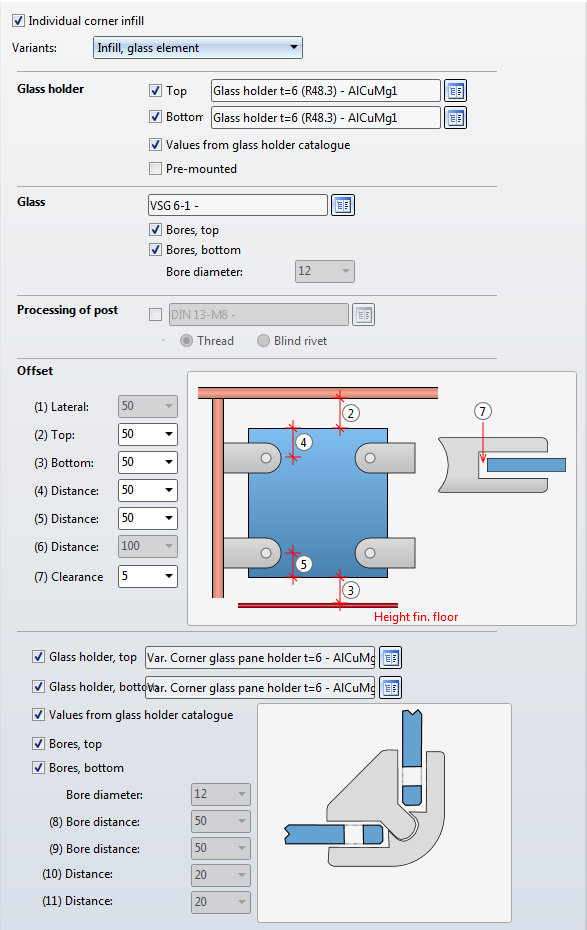
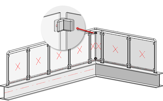
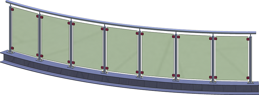
Example of a glass railing with individual corner infill
No usage is assigned to glass panes. This enables you to use the DEFAULT(GLASSCHEIBEN) configuration for the workshop drawing.
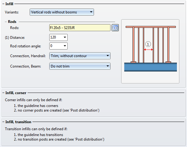
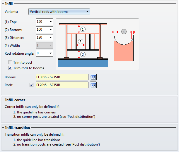
Vertical rods
Here you can define vertical rods which can be rotated, in addition to the knee rails. Depending on the type of the chosen variant the connections will be with the beam, with the handrail, the post or the boom. For example: the vertical rods can be inserted in the handrails or can be trimmed at the handrails, with or without contour. Furthermore, you can specify whether the booms on the posts and the filling rods on the booms are to be trimmed.
(1) Inserted in the handrails with gap, (2) without trim, (3) trim with contour
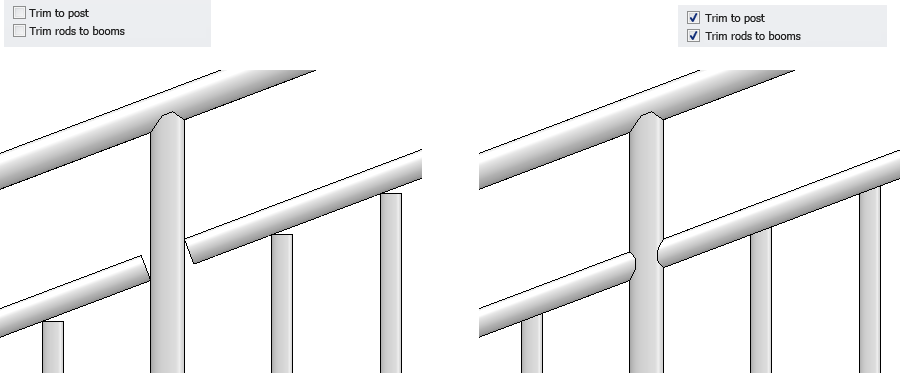
Vertical rods with booms - untrimmed (left) and trimmed (right)
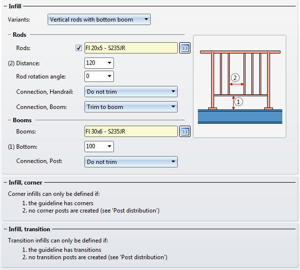
For vertical rods with booms, bottom boom or frame, you select the booms, the bottom boom or frame, complete with rods and spacers from the catalogue.
For round to round connections you can also specify the parameter Width, referring to the width of the obtuse end.
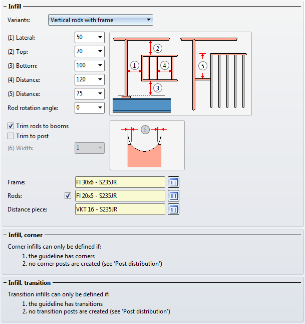
By deactivating the Rods checkbox you can also create railings that have only frames, but no rods.
(1) Frame with rods; (2) Only frame
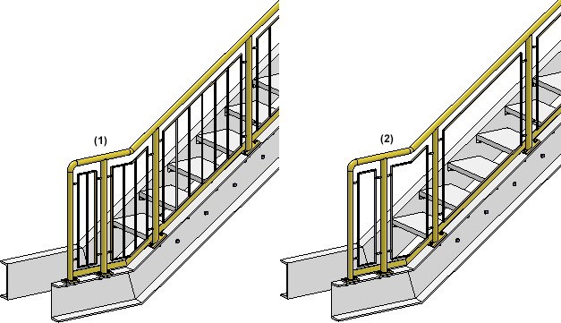
If you want to place rods in corners of beam frameworks, activate the Corner rod checkbox. For transition infills, use the Individual transition infill checkbox. If this checkbox has been activated, one rod will always be placed exactly into the corner or in the transition area. If the corner rod should be aligned to the angle bisector, please activate the Align angle bisector checkbox.
Please note that corner or transition rods can only be placed if no corner or transition posts have been set.
Example of a corner infill: (1) corner rod, bisecting alignment, (2) corner rod, no bisecting alignment
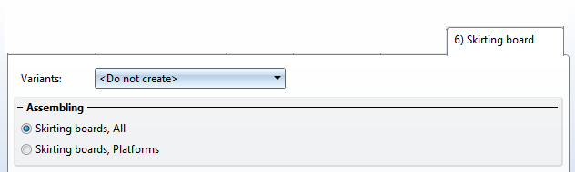
6) Skirting board
Available are skirting boards of flat steel.
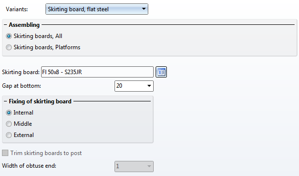
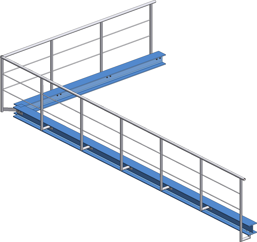
Beneath Assembling you can specify by activating the corresponding option whether the skirting boards are to be used everywhere, or only on platforms, i.e. only in the horizontal area, with oblique trimmings (see image below).
Enter the distance between skirting board and upper beam side in the Gap at bottom input field, and specify the fixing of the skirting board.
Example - Step 3 - Component selection
In our example we will apply the ISD settings - with one exception - the railing is to be created without skirting boards.
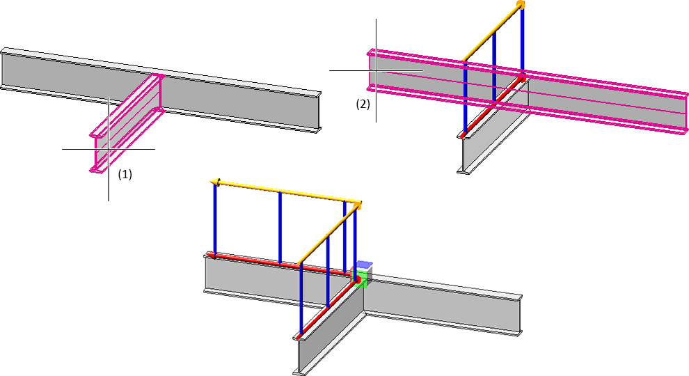
Connecting the railing components
Besides the components, you can create the following connections via the same-named tabs:
- Post - Substructure (1)
- Post - Handrail (2 - 4)
- Handrail - Handrail (5)
- Skirting board - Skirting board (6)
If you do not want to create a connection, select the <do not create> option in the corresponding selection box.
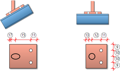
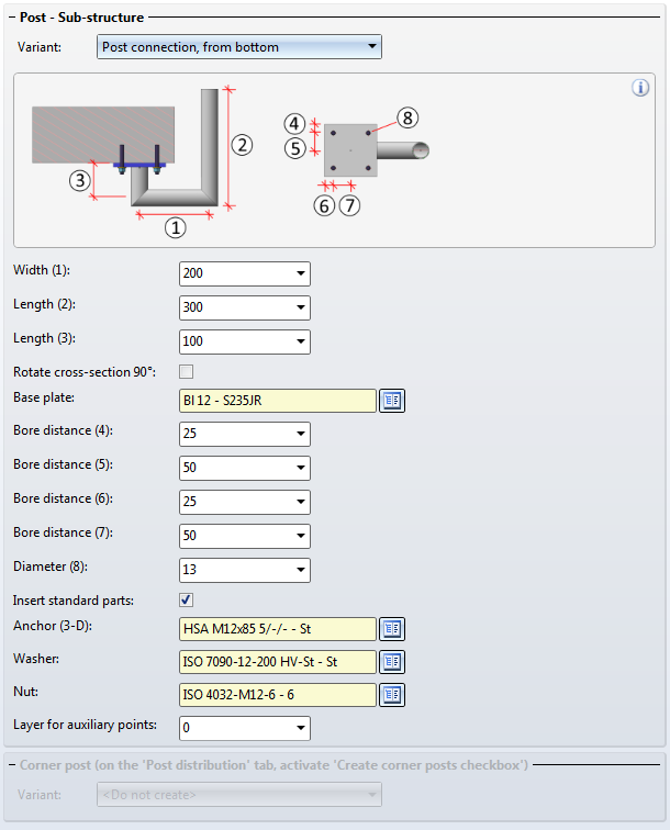
Post - Substructure
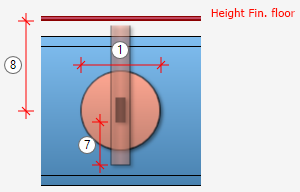
Here you specify the fixing of the posts to the beams The posts can be mounted either on the top, side, bottom, or bottom with flat steels to the beam - with or without stiffeners. A bore grid for the base plate can also be selected - possible options are:
- No bores,
- 2 bores or
- 4 bores.
The post connection for the substructure can now be determined separately for
- start, intermediate and end posts and
- corner posts.
Start and end posts can also be determined individually, i.e. independently of the intermediate posts. To do this, you must activate the corresponding checkbox at the top of the dialogue window.
Railing with lateral connection of the start, corner and intermediate posts and connection from bottom for the end post
Please note the following when selecting the post connections: It is only possible to combine the variants Post connection, lateral and Post connection, bottom. If, for example, you have selected the variant Post connection, lateral for a corner or intermediate post and the variant Post connection, top for the start or end post, then the installation is not possible and a corresponding error message appears, e.g. 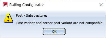
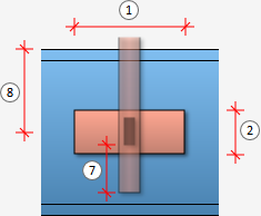
Post connection, top
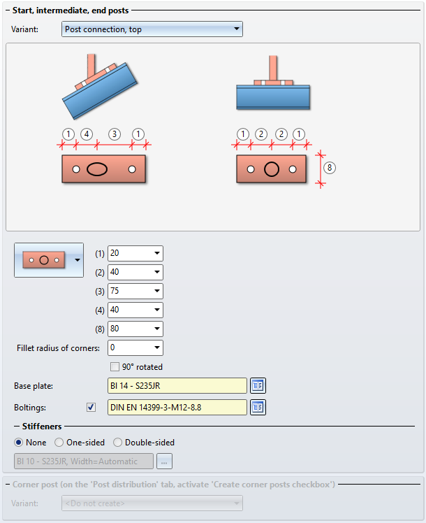
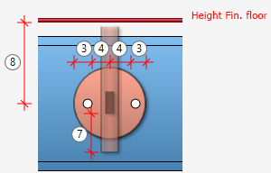
Depending on the selected bore grid, the possible options are:
| Bore grid |
Input values |
|
|---|---|---|
| Rectangular, no bore |
|
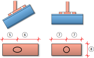
|
| Rectangular, 2 bores |
|
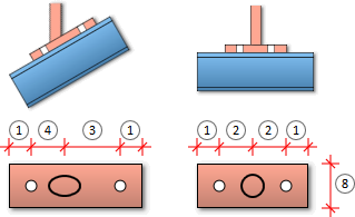
|
| Rectangular, 4 bores |
|
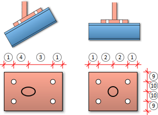
|
|
Round, no bore |
|
|
|
Round, 2 bores |
|
|
|
Round, 4 bores |
|
|
|
One-sided, no bore |
|
|
|
One-sided, 1 bore |
|
|
|
One-sided, 2 bores in transverse direction |
|
|

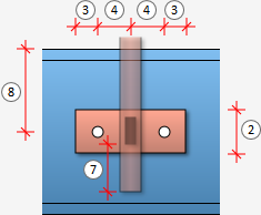
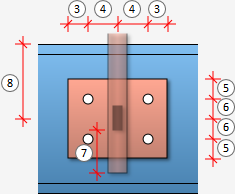
Post connection, lateral

Depending on the selected bore grid, the possible options are:
| Bore grid |
Input values |
|
|---|---|---|
| Rectangular, no bore |
|
|
| Rectangular, 2 bores |
|
|
| Rectangular, 4 bores |
|
|
|
Round, no bore |
|
|
|
Round, 2 bores |
|
|
|
Round, 4 bores |
|
|
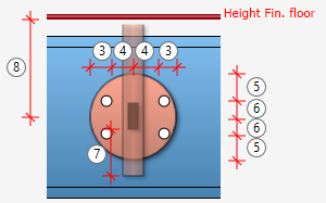
![]() Depending on the kind of the selected beams they will be divided into different sections. The first beam belongs to section 1. HiCAD checks whether the next beam lies on the same plane. If so, it also belongs to section 1. If it does not lie on the same plane, section 2 will start with this beam and so forth. For the lateral post connection the Distance, plate centre can be set individually for each section. If the distance should be the same for all areas, activate the All same checkbox.
Depending on the kind of the selected beams they will be divided into different sections. The first beam belongs to section 1. HiCAD checks whether the next beam lies on the same plane. If so, it also belongs to section 1. If it does not lie on the same plane, section 2 will start with this beam and so forth. For the lateral post connection the Distance, plate centre can be set individually for each section. If the distance should be the same for all areas, activate the All same checkbox.
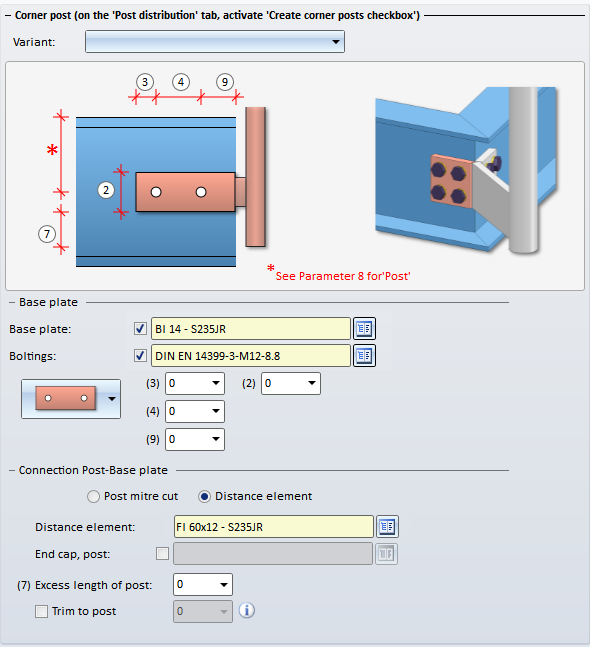
There are two new possibilities available for connecting posts and base plates:
- Post mitre cut
Instead of a distance plate, the same beam as for the post will be generated and a mitre cut will be applied to the newly created beam and the post beam.
- Distance element
A distance element for the post beam and - if desired - an end cap will be installed. The excess length of the post can be determined. If the distance element should be trimmed to the post, the respective checkbox has to be activated and the width of the obtuse end has to be entered.
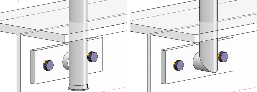
Left: with distance element (trimmed) and end cap, right: post mitre cut
If the connection is made with a distance element, there is a possibility that the distance element penetrates the base plate when connecting laterally. To do this, activate the checkbox Penetration of base plate and specify the Clearance, the Corner radius and the Shortening of distance element.
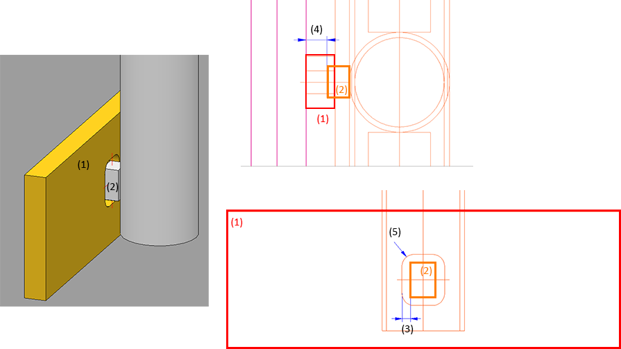
(1) Base plate, (2) Distance element, (3) Clearance, (4) Offset, (5) Corner radius
Connection from bottom
Specify the following values:
|
Inputs |
|---|
|
Connection from bottom with flat steels
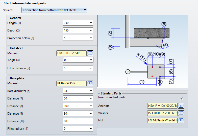
Specify the following values:
|
Inputs |
|---|
|
If you have activated the Create corner posts checkbox on the Post distribution tab, you can specify the corner post connections here. The following variants are possible:
- Do not create
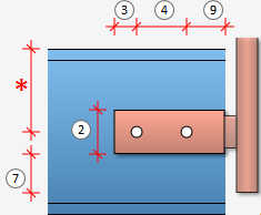
- Corner post connection, lateral
Depending on the selected bore grid, the possible options are:
| Bore grid |
Input values |
|
|---|---|---|
| No bore |
|
|
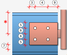
| 2 bores |
|

|
| 4 bores |
|
|
For the connection of posts and base plates the same options are available as for "normal" post connections.
Please note:
Even if you activate the All posts equal checkbox on the Post tab, the settings on the tabs Post - Substructure and Post - Handrail will not be considered for corner posts and transition posts! The connections on corner posts and transition posts must therefore be reworked manually.
Post - Handrail
Here you specify the connection of post and handrail.
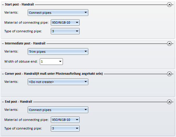
If you want to use the same variant for all posts, please activate the All posts equal checkbox.
|
Allowed connections |
|||
|---|---|---|---|
|
Start post - Handrail (3) |
Intermediate post - Handrail (2) |
Corner post - Handrail (2) |
End post - Handrail (4) |
|
|
|
|
|
to Do not create / Do not insert. In addition, a lateral offset to the handrail must be entered on the Post tab. |
Example of a connection Intermediate post - Handrail: 1) Connection with mandrel, (2) Trim pipes
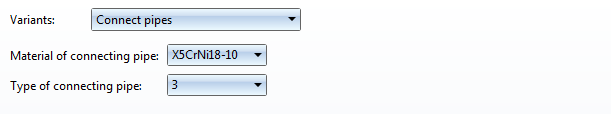
For the Connect pipes variant you need to choose the material for the connecting pipe and then its type. The latter determines the bend radius:
- 2 (Bend radius approx. 1,0 x Outer diameter)
- 3 (Bend radius approx. 1,5 x Outer diameter)
- 5 (Bend radius approx. 2,5 x Outer diameter)
- 10 (Bend radius approx. 5 x Outer diameter)
- 20 (Bend radius approx. 10 x Outer diameter)
For round to round connections the parameter Width of obtuse end can be specified if the Trim pipes option has been selected. Normally, a pointed end (1) is created on the pipe after the trimming. Use the Width of obtuse end(2) parameter to specify how the pointed end on the post is to be cut off.
Please note that a connection of corner posts and handrails is only possible if the Create corner posts checkbox has been activated on the Post distribution tab.
Handrail - Handrail
Here you define the connection of the handrails.
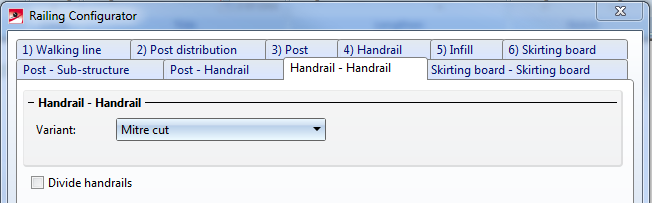
Allowed connections are:
- Mitre cut,
- Connect pipes.
Handrails can also be divided, e.g. in order to insert plug-in profiles or flat steel joints for long railings. Just activate the required checkbox.
If the checkbox is active, the variant for handrail division and the division of the handrail can be specified by segments.
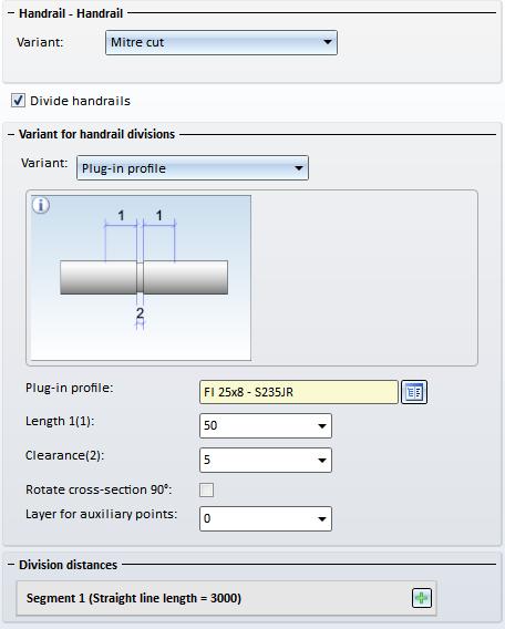
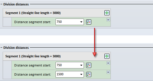
The divisions can be defined either by specifying the distance from the segment start, or by specifying a division point.
|
|
New division Click on this symbol to add a new division, e.g.:
Enter the distance of the division from the segment start in the input field. |
|
|
New division at selected point Click on this symbol do define the division by specifying a division point. |


Divisions can be deleted at any time by clicking on the  symbol at the top right next to a division.
The following variants for handrail division have been predefined:
- Straight cut,
- Plug-in profile and
- Flat steel joint.
The image below shows a railing with divided handrails.
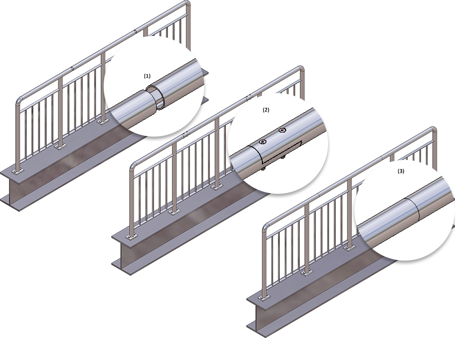
(1) Variant: Plug-in profile, (2) Variant: Flat steel joint, (3) Variant: Straight cut
Skirting board - Skirting board
Here you define the connection of the skirting boards. Here, mitre cuts are possible.
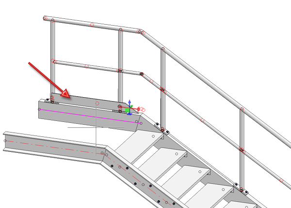
Example, Step 4 - Selection of connections
Use the ISD default settings and close the dialogue window with OK. The first railing will be inserted.
Example, Step 5 - Repeat Step 1 to Step 4 for the right stair stringer
Complete the example by repeating Steps 1 to 4 for the right stair stringer. Call the railing Configurator again and identify the right stringer beams (1) and (2).
The last chosen parameters will be shown in the Railing Configurator dialogue window. With the exception of the Offset, which needs to be entered in negative Y-direction here, apply all of those settings by clicking OK. The railing will then be generated.
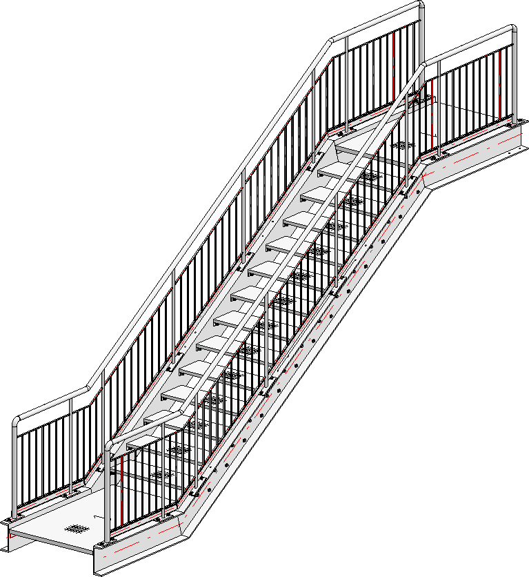
Finished railing
An example and tips for the placing of railings with equal post distances on multi-storey staircases can be found here.

Railing Configurator - Railings Along Edges • Steel Engineering Functions