Rectangular Plate
Steel Engineering > Plate, new > Rectangular
plate
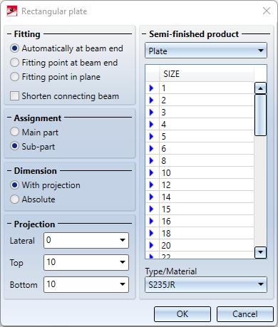
You use this function to insert rectangular plates, e.g. front plates for beams. Once you have called the function, the Rectangular plate dialogue window is displayed. Not all options and fields are always active. This depends on the option chosen in the Fitting area.
|
Fitting |
Various options are available for the insertion of the plate: The checkbox Shorten connecting beam is only available for the fitting type Automatically at beam end. |
|
Semi-finished product |
Here you select which semi-finished product is to be inserted:
In the list below, select the sheet thickness or, for flat/wide flat steel, the width and thickness. Under Type/Material you can change the material. There are various standardised materials to choose from. |
|
Assignment |
The plate can either be inserted as a main part or as a sub-part to the beam. Please note the following:
|
|
Dimension |
The options With projection and Absolute are only available for the fitting type Automatically at beam end and then only for the semi-finished product type Plate. For the other fitting types, you specify the width and height for sheet metal or the height for flat/wide flat steel under Dimension. |
 identifier) or not.
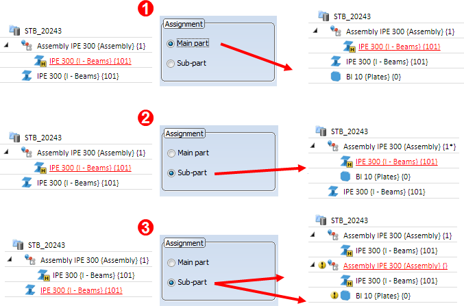
If you have activated the desired options and entered all required data, click OK to exit the Rectangular plate window. The displayed dialogue window depends on the selected type of insertion.

Fitting: Automatically at beam end
The front plate is automatically fitted at the selected beam end. The centroid of the connecting surface of the plate lies in the end point of the beam axis.
|
Dimension |
You define here how you want the plate size to be determined:
Please note that the With projection option is not possible for fitting flat steel and broad flat steel . In these cases, choose the width and thickness in the selection list and specify the height. |
|
Connecting beam: Shorten |
If this checkbox is active, the beam to which you want to attach the plate is shortened by the amount of the plate thickness. |
|
SIZE |
If you have chosen Plate as the plate type, select the plate thickness in the selection list. When fitting Flat steel or Wide flat steel, choose the width and thickness from the selection list. |
Once you have completed all your entries, click OK to exit the Rectangular plate window. Next, specify the beam end for fitting the front plate
Left: (1) Width, (2) Height, (3) Thickness, Right: (1) Top projection, (2) Bottom projection, (3) Lateral projection
![]() Please note:
Please note:
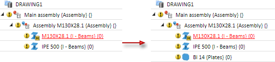
If the reference beam is a main part that does not belong to an assembly, an assembly will be formed, with the beam as assembly main part and the plate as sub-part.
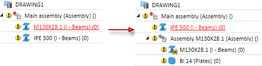
If the reference beam belongs to an assembly, the plate will also be assigned to this assembly as a sub-part.
Fitting: Fitting point at beam end
This function only allows you to specify the dimensions of the plate directly. The With projection and Connecting beam: Shorten options are not available. This means the following:
- You enter the width and height for plates. You choose the plate thickness in the selection list.
- You choose the width and thickness for flat steel and broad flat steel in the selection list and enter the height.
Once you have completed all your entries, click OK to exit the Rectangular plate dialogue window and identify the beam end for fitting the front plate. The plate is displayed in enlarged form. Next, identify a fitting point on the plate and its position in the drawing.
(1) Beam fitting point, (2) Plate fitting point
Fitting: Fitting point in plane
As with the Fitting point at beam end option, you can only specify the dimensions of the sheet directly here. The With projection and Shorten connecting beam options are not available. In contrast to the Fitting point at beam end option, however, the plate is rotated to a plane here and only then fitted by specifying the fitting point on the plate and its position in the drawing.
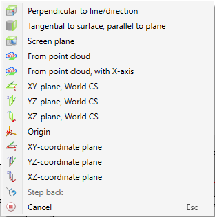
Once you have completed all your entries, click OK to exit the Rectangular plate window and identify the beam for plate assignment. Next, specify the plane to which you want the plate to be rotated (same procedure as with the creation of processing planes): Identify either a plane, a surface, an edge or a point and then follow HiCAD's user instructions. Or use the right mouse button to activate a context menu containing more plane specification options:
The plate is rotated to the plane and displayed in enlarged form. Identify a fitting point on the sheet and its position in the drawing.
(1) Beam with fitting point and plane, (2) Source plate, (3) Plate rotated to the plane
