"Civil Engineering functions" docking window > Steel Engineering > Connections > Front side to front side > Front plate > Purlin joint, 2 plates with mitre cut acc. to DAST PM/PQ (2415)
This function connects two beams by a rigid joint. Permitted are I-beams and U-beams, which must be aligned. The installation can be user-defined or - with corresponding beams - based on a table according to DAST PM or PQ.
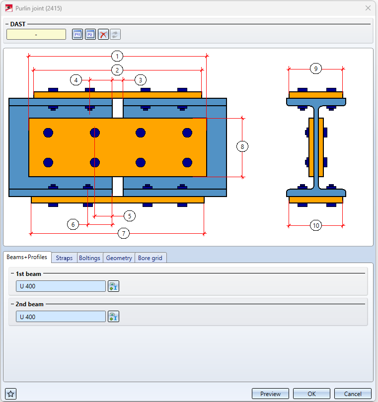
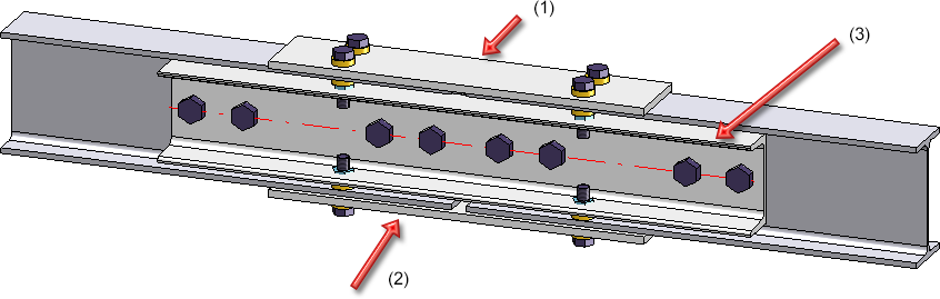
In the user-defined configuration, the joint can be created with one strap each on the upper and lower flange as well as on the web, whereby all straps as well as the corresponding screw connections and hole patterns can be set separately. U-beams or flat steels are possible as straps. The connection can be flush or with clearance.
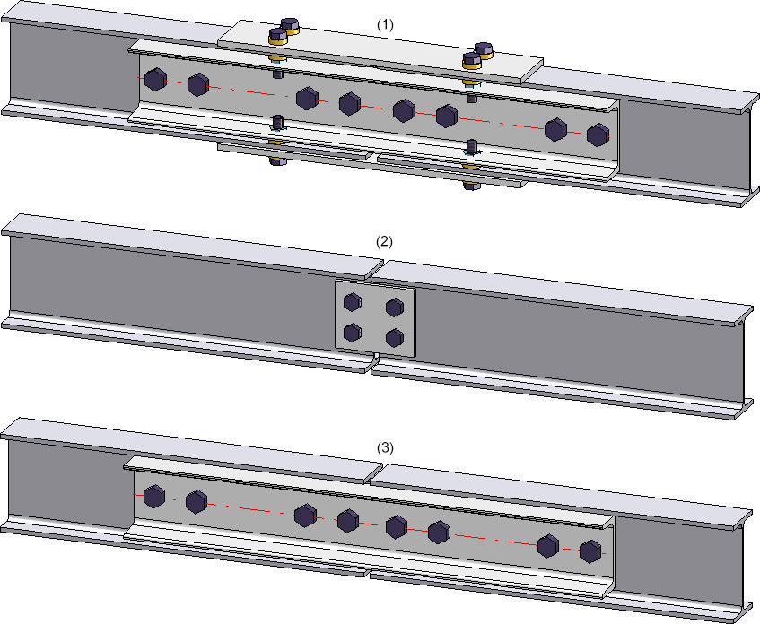
(1) User-defined, (2) DAST PQ, (3) DAST PM
Buttons
|
|
The settings of the dialogue can be saved as favourites and reused at any time. To do this, click on the |
|
Preview |
When the dialogue window is open, you can use the Preview button to display a preview of the connection created by the current settings. You can also enlarge and reduce the image section with the Zoom functions. |
|
OK |
You start the generation of the connection with OK. The status of the generation is indicated by a progress bar in the status bar. After the connection has been generated, the dialogue window is closed. |
|
Cancel |
With Cancel the dialogue window is closed without generating the connection. |

![]() Please note:
Please note:
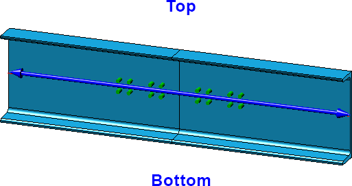
- In the drawing, while entering the required data, it is marked where the top and bottom are.
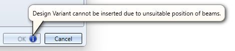
- If it is not possible to insert the joint with the current settings, this is indicated in the dialogue window by the symbol on the OK button. If you point to this symbol with the cursor, a corresponding explanation is displayed, e.g.
- The straps are assigned to the assembly of the first beam. The boltings can either be combined in a structure assembly with the name Loose parts or assigned as assemblies with the name Bolted connection to the assembly of the first beam.

User-defined insertion or insertion according to DAST
The insertion of the purlin joint can take place user-defined or based on a DAST table.
The typefied connections in steel engineering according to DSTV/DASt are stored in tables in HiCAD. To take over the data for the corresponding parts like plates, bolts etc. from these tables, first select the connection type. To do this, click on the  or
or  symbol and select the desired connection in the window that then appears, e.g.:
 .
.
Click on the Extended button to display further data of the possible connections. If necessary, set one or more filters - such as bolt selection, strength, etc. - to limit the selection.
Select the desired connection and exit the window with OK. The name of the selected DAST connection is then displayed in the input field.
After selecting a DAST connection, the content of the tabs is adjusted accordingly. Settings that are not possible for the selected connection are greyed out. If a DAST connection is changed, HiCAD checks whether the connection is still DAST-compliant. If this is not the case, then the DAST selection field is marked by the  symbol. If you point the cursor to this symbol, a corresponding message is displayed, e.g.:
To restore the original settings, click on the  symbol. To remove the DAST assignment altogether, e.g. because the connection is to be user-defined without using DAST tables, click on the
  symbol.
User-defined insertion
With custom insertion, you can also use the settings from DAST tables as default values and then configure the purlin joint as desired.
Configure purlin joint
Die Konfiguration des Anschlusses erfolgt über die Registerkarten des Dialogfensters:
Beams + Profiles
After calling the function, first select the two beams at the reference ends. As already mentioned, these must be aligned I-beams or U-beams. The beam type is then entered in the respective input field.
If you want to change the beam selection, click on  .
.
Straps
Here you define whether you want to create straps mounted to the beams and, if so, which ones:
- On flange (Top),
- On flange (Bottom), and
- On web.
Activate the corresponding checkboxes and choose the semi-finished product from the catalogue  .
.
Boltings
For the selected straps you define the boltings here, e.g. type of bolt, hole diameter etc. To do this, click on the symbol and then compile the components of the bolted connection. The procedure here is similar to the Steel Engineering bolting function.
The bolting will only be inserted if the Create checkbox is activated.
If the bolting direction is to be inverted, activate the Invert checkbox.
If you want to use the same bolting for the bottom flange as for the top flange (and vice versa), click on the Apply to other side  symbol.
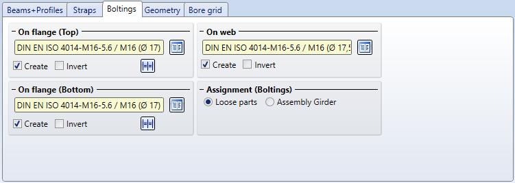
The boltings can either be combined in a structure assembly with the name Loose parts or assigned as assemblies with the name Bolted connection to the assembly of the first beam
Geometry
The size of the straps is determined on this tab. The meaning of the input fields can be seen in the graphic of the dialogue window.
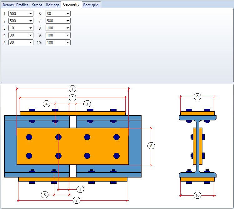
If you have selected a DAST connection as a template, some fields will be greyed out, depending on the connection type.
If the connection is not flush but with clearance (value 3), then both straps are shortened by half the width of the clearance.
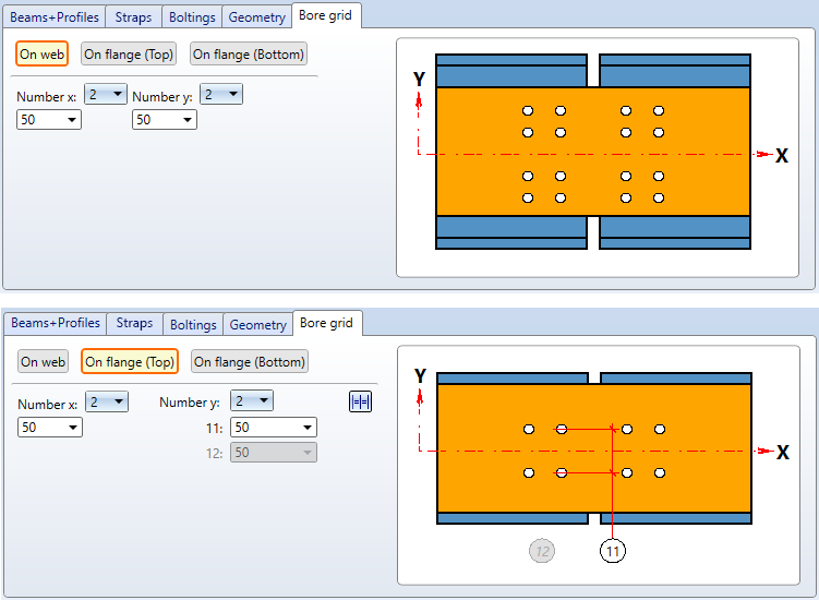
Bore grid
For the selected straps you determine here the number and the arrangement of the respective boltings, i.e. the number of boltings in X- and Y- direction. The grid can be set separately for the straps on the top and bottom flange as well as on the web. The settings of the Bore grid are symmetrical for the 1st and 2nd beam.
The maximum number of boltings per beam can be found in the following table:
|
Max. number of boltings |
x |
y |
|---|---|---|
|
Web |
4 |
8 |
|
Flange, top |
4 |
2 or 4 |
|
Flange, bottom |
4 |
2 or 4 |
Select the desired number and enter the distances between the boltings. The distance in X-direction between the boltings of the first and second beam is defined by the values (3) and (5) on the Geometry tab.
An example of a bore grid on the web
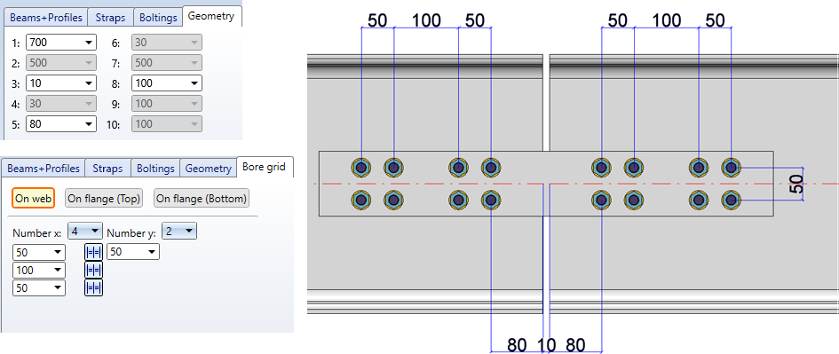
With a click on the symbol you can equate the distances.
If you want to use the same bore grid for the bottom flange as for the top flange (and vice versa), click on the Apply to other side symbol.

Connections + Variants (3-D STB) • The Catalogue System for Connections+Variants (3-D SE)