"Civil Engineering functions" docking window > Steel Engineering > General > Purlin joint (3204)
With this design variant, you connect a girder and a purlin with a sheet metal part (1-fold or 2-fold) or an L-bracket that is bolted to the purlin and bolted or welded to the girder. The connection can be made on one or two sides. The purlin can be any 3-D part here.
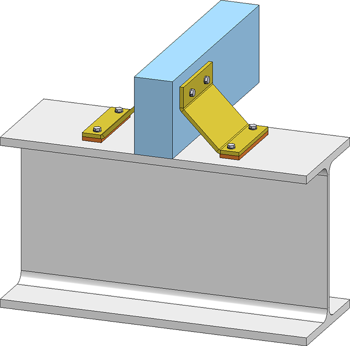
2-sided purlin joint, with 2-fold sheet and connecting plate, bolted to girder and purlin
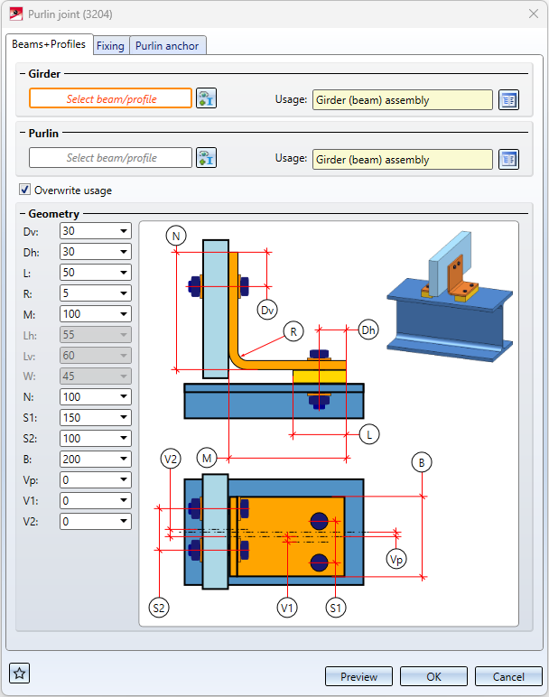
During input, the current settings are visualised in the drawing.
By clicking on the Preview button, you can display an exact preview of the purlin joint - based on the currently entered data. If you want to correct the data, make the changes and click Preview again to update the preview. Click OK to install the purlin joint with the current data and close the dialogue window. If you exit the dialogue window with Cancel, the function is cancelled without insertion or without changing the connection.
The settings of the dialogue window can be saved as favourites and reused at any time. To do this, click on the  symbol at the bottom left of the dialogue window to activate the context menu. You can find more information on the administration of favourites in the Manage Favourites topic of the HiCAD Basics Help.

Configure purlin joint
The purlin joint is configured via the settings on the various tabs of the dialogue window.
Beams+Profiles
On this tab you select the girder and the purlin and you define the dimensions of the purlin joint.
Specify the girder and the purlin in your drawing. Click on the  symbol to change the selection.
Which input fields are active on this tab depends on the selected purlin anchor.
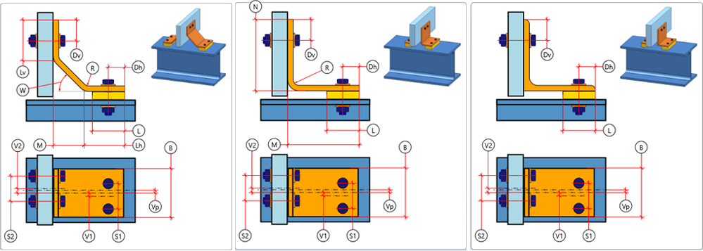
From left: 2-fold sheet, 1-fold sheet 1x gekantet, L-bracket
In the Usage field, you can define which usage is to be assigned to the girder or purlin assembly. If a usage is already assigned to the assembly, the checkbox Overwrite usage can be used to specify whether this usage should be retained or replaced by the usage selected here.
Fixing
Here you determine how the sheet metal part/L-bracket is attached to the purlin and the girder.
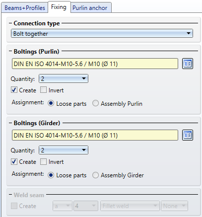
The mounting to the purlin is done by bolting. For mounting the purlin anchor to the girder, both bolting and welding are possible.
Boltings (Purlin)
The bolt and hole can be selected by clicking on the  symbol directly in the standard parts catalogue. A maximum of two bolts (max. 2) can be inserted.
If the direction of the bolting is to be inverted, activate the checkbox Invert. If the bolting is not to be created, deactivate the checkbox Create.
The parts of the bolting can be combined separately in a structure assembly with the name Loose parts or assigned to the assembly of the girder.
Boltings (Girder)
The bolting is defined in the same way as the bolting on the connecting part.
Weld seam
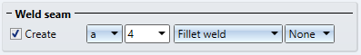
If you have selected Weld as the Connection type, you can determine here whether the weld seam is to be created. If yes, select the type of thickness designation, the weld seam thickness, the weld seam type and the inspection category.
Purlin anchor
Here you determine the type of the fixing.
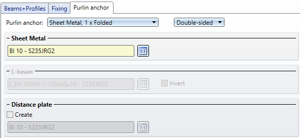
For purlin anchors the following options are available:
- Sheet Metal, 1 x folded,
-
Sheet Metal, 2 x folded and
- L-bracket.
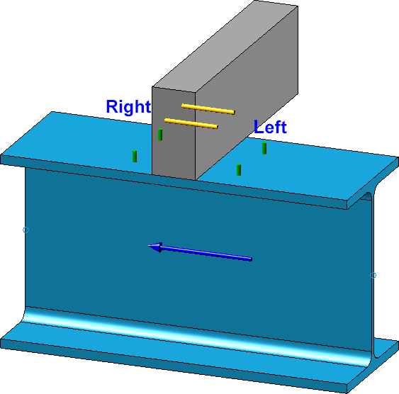
For the fixing you have the options Right, Left or Double-sided.
Select the desired sheet metal part/L-bracket from the standard parts catalogue by clicking on the  symbol. The sheet metal parts are in the catalogue Factory standards > Sheets.
In addition, a Distance plate can be inserted. To do this, activate the checkbox Create and then select the desired plate. The plate is assigned to the assembly of the girder.

Connections + Variants (3-D SE) • Dialogue Window for Connections (3-D SE) • The Catalogue System for Connections+Variants (3-D SE)