
Project: Configuration Management
Up to now, the Configuration Editor at System settings > Catalogues could be used to define how catalogue changes should be handled in HiCAD. From HiCAD 2020 SP2 onwards these settings are no longer available in the Configuration Editor . Instead, the switch Track catalogue changes is now available at  Settings in the Catalogue menu.
If the switch is active, the catalogues are regularly checked during a HiCAD session to ensure that they are up-to-date. This actuality check can, however, significantly impair performance in some situations. If the switch is active, then this is indicated when HiCAD is started. By default, the switch is inactive by default, that is, the catalogues are loaded in HiCAD only once, when starting HiCAD. After that, the system does not check whether more recent data is available. To update the catalogues after changes, the function Reload is available. This offers the possibility to update catalogues after changes without having to leave HiCAD and without having to accept performance losses due to the constant check for up-to-dateness.
The current status of the switch (active/inactive) is entered into the Windows Registry. If the switch is active, the following message is displayed when starting HiCAD.
If the Enter constraints checkbox in the HCM settings for sketches is active or if a sketch is parameterized manually, the sketch points are highlighted in colour. From SP2, this also applies to isolated points in a sketch.
You define the size and colour of the highlighting in Configuration Editor at System settings > Sketch HCM.
The settings of the 3-D Import  function can now be saved as favorites for the different file formats. To do this, click on the
  icon in the dialogue. You can find more information on the management of favourites in the Manage Favourites topic of the HiCAD Basics Online Help . In the Configuration Editor at Interfaces > Import, you can determine which favourite will be used as default in the import dialogue.
The following settings in the Configuration Editor are no longer necessary due to the Favourites management:
When generating bills of materials, the lengths of similar straight pipes can be combined. The Combine pipe length lists in BOMs checkbox is available in the Configuration Editor at Plant Engineering > Bills of materials.
If the checkbox is active, similar pipes are combined to a single pipe when generating bills of materials. The length of this pipe is equal to the sum of the individual pipe lengths. By default, the checkbox is inactive.
As of HiCAD 2020 SP1, you can use the Configuration Editor to define the procedure for starting the itemization in a model drawing that still uses the itemization up to HiCAD 2017. To do this, open the Configuration Editor and choose System settings > Itemisation > Switch to 'Standard itemisation used since HiCAD 2018'.
Previously, pasting from the HiCAD clipboard was performed "in a loop", i.e. after pasting from the clipboard, the function remained active, so that you could paste the clipboard contents several times at different positions in the model drawing.
From HiCAD 2020 SP1 onwards, this behaviour can be defined in the Configuration Editor at System settings > Miscellaneous by activating / deactivating the Repeated paste from clipboard checkbox.
For complex model drawings, especially when updating views in HiddenLine mode, waiting times may occur. To reduce this time, the following parameters are available in the Configuration Editor at System settings > Visualization > Views:
The Steel Engineering BOMs
are no longer available for new installations from HiCAD 2020 SP1. In the HiCAD configuration these templates will be replaced by the template hicad_stahlbau from SP1 on. This applies in particular to the usage-dependent setting in the Configuration Editor at Automatic drawing derivation> Steel Engineering > Usage-dependent > ......> View group > File name: BOM.
For update installations everything remains unchanged.
In Configuration Editor at Steel Engineering > Notch, the default value for Offset from web has been changed to 0. The previous default value was 10.
In the Configuration Editor at PDM > Management+BIM, the Type of part referencing parameter does no longer exist. This means that the parts of the automatically generated drawing are referenced unilaterally with the initial model drawing and are marked accordingly in the ICN with the  symbol. If changes are made to the model, the drawing can be updated automatically. This does, however, not apply vice versa.
Similar to the manufacturing documents created with the Management+BIM module, a script for rework can now be automatically executed when saving model drawings controlled with Management+BIM. For this purpose, the Rework of drawing selection box in the Configuration Editor at PDM > Management+BIM > Production drawings has been expanded.
If you have selected the generation of n-digit drawing numbers in Configuration Editor at PDM > Management+BIM > Production drawings, you can use the parameter Drawing number generation from HiCAD 2020 SP1 onwards to specify how the numbering is to take place:
Select None to deactivate numbering completely. The default setting is By projects.
In the Configuration Editor at PDM > Management+BIM, you can now define whether the associated assemblies, e.g. welded assemblies, should be determined for individual parts (beams, profiles, plates, sheets and general parts). The parameter Output associated assemblies is available for this purpose. If this parameter is set to Yes, the association is determined and assigned to the HELiOS article attribute COMPONENT_REFASSEBMLY. This can be useful for the BOM output, for example. The default setting is No.
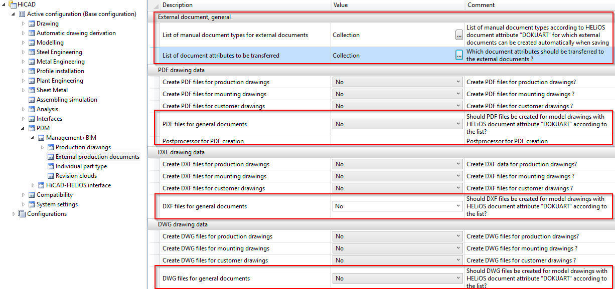
In practice, it often happens that overview drawings of a model drawing are created manually in a separate sheet area. These drawings contain, for example, sectional views, cut-outs, shortened views, detail views, etc., and are intended to illustrate how the model is realized. These sheet areas are not taken into account when creating external production documents.
In order to be able to manage these documents together with the corresponding model in HELiOS, HiCAD offers the possibility to automatically create a PDF, DXF and/or DWG file of the respectively active model or sheet area directly when saving a model drawing.
Whether and which formats are generated is determined via the Configuration Editor at PDM > Management + BIM > External production documents, where you will find the required parameters.
In the Configuration Editor, you can now use the settings at PDM > Management + BIM > Production drawings > Title blocks to specify that customer-specific and/or usage-dependent title blocks are to be used in production drawings.
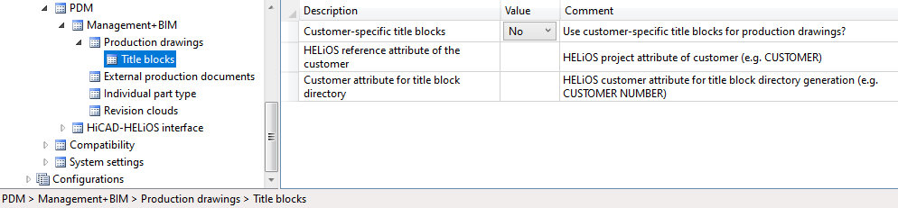
HiCAD's scope of delivery includes corresponding title block templates and the corresponding drawing frames. These templates and frames can be found in the HiCAD subdirectory templates\Module_3DSteel\BIM\szenen\BIM:
Loose flanges in Plant Engineering can be inserted as regular flanges from SP1 onwards. The loose flange is pushed down from the straight pipe by a fixed excess length. This value can be set in the Configuration Editor at Plant Engineering > Layout plan > Insert loose flange with excess length.
If the automatic assignment of constraints is activated in the Sketch HCM settings (Sketch > HCM > Tools > Settings), the start and end points of the sketch lines and arcs are represented by small blue points from SP1 onwards. The size of the points can be set in the Configuration Editor at System settings > Sketch HCM with the Size of highlighted sketch points parameter.
The settings of the ABWPOL.DAT file have been moved to the Configuration Editor (ISDConfigEditor.exe).
You now find the settings for the neutral axis for approximative sheet development at Sheet Metal > Default setting.
The settings
have now their own node in the Configuration Editor, at Compatibility > Views.
From HiCAD 2020, the shortening of views is also possible for shaded views.
Previously, views were created with the display type
is always shown unabbreviated, even if the view was actually shortened. For drawings created with a version before HiCAD 2020 and containing such views, you can define in the Configuration Editor at Compatibility > Views how to proceed when opening these drawings.
The default settings for fonts can now be specified separately for 2-D and 3-D texts in the Configuration Editor. You find the corresponding parameters at Drawing > Annotations > Text.
For assemblies, the dimensions of the parts belonging to the assembly can be used to automatically generate the attributes Length, Height and Width of the assembly and enter it in the assembly attributes. All solid parts belonging to the assembly are included in the calculation, with the exception of standard and purchased parts with the insertion type Site assembly.
Whether and when the assembly dimensions are calculated when parts are changed can be set in the Configuration Editor, namely at Modelling > Part properties > Calculate assembly dimensions.
When generating the DXF export files for Sheet Metal blanks, the orientation of the polylines in the created DXF file will now always be consistent (i.e. always either clockwise or anticlockwise), since CAM programs require this for determining the outer / inner side when calculating the tool paths of the milling tools.
Choose Sheet Metal > Sheet development > Export... in the Configuration Editor to choose between clockwise (activate checkbox) or anticlockwise orientation (deactivate checkbox).
The settings for the representation of the beam orientation at System settings > Visualisation > Indicate orientation of active Steel Engineering beam have been modified:
The orientation is only shown when a beam is inserted. This is the default setting.
The orientation is always shown.
The F6 switch is no longer available.
In previous versions, dimensions were always assigned to the active part during their creation. From HiCAD 2020 onwards, you can assign the dimensions either to the active part or to the part to which the 1st dimension base point belongs. This behaviour can be determined via the Set parameters for new general dimensions function, on the System tab of the dialogue window. The parameters of this tab can be preset via the Configuration Editor, at System settings > Annotations > Dimensioning, 3-D > Interactive dimensions > Dimension assignment. The default setting is Active part.
Like any other part, assemblies, too, have a part coordinate system. This coordinate system can either (as previously) be automatically determined by HiCAD, or (from HiCAD 2020 onwards) determined by you during creation of a dummy assembly or during forming of an assembly from existing parts. For this purpose, a new parameter is available in the ISD Configuration Editor at Modelling > Part creation > Assembly.
The detail drawings created with the Management+BIM module are always stored on Sheet 2 of the drawing. When printing via the HELiOS/HiCAD Spooler, all sheets will be printed - depending on the setting - i.e. also Sheet areas without production drawings such as Sheet 1.
By setting the parameter Delete unused Sheet areas to Yes, it is now possible to specify in the Configuration Editor at PDM > Management+BIM > Production drawings that Sheet areas with no production drawings are deleted. The default setting is No.
When creating/updating external CAM data in the formats DSTV-NC, DXF, DWG, NCW/NCX and STEP, and drawing data in the formats DXF, DWG and PDF, the corresponding files can also be automatically exported to the Windows file system if required. The appropriate parameters are available in the Configuration Editor at PDM > Management+BIM > External production documents.
By default, the Management+BIM module works project-related, i.e. the managed parts are usually clearly assigned to one project. When installing parts with reuse in other projects, such as purchased parts, you must assign the article master manually, as these parts are ignored by the BIM automatisms.
From HiCAD 2020 onwards, this behaviour can be changed in the Configuration Editor at PDM > Management + BIM. There, set the parameter Main and sub-projects to Yes.
As of HiCAD 2020 the following changes to the dimensioning rules apply:
have been removed from all views. As a result, die dimensioning rules of this configuration has changed (only applicable to new installation).
the dimension type Individual dimension is now also permissible, in addition to the dimension type Chain dimension. If you choose Chain dimension as the dimension type, the chain of dimension will be lengthened according to the selected reference, and becomes a chain dimension. If you choose Individual dimension, only the length of the cut will be dimensioned. When updating model drawings from versions older than 2020, only the cut will be dimensioned, and no chain dimension will be created!

Configuration Management (CM) • User Interface (CM)
|
© Copyright 1994-2020, ISD Software und Systeme GmbH |
Data protection • Terms and Conditions • Cookies • Contact • Legal notes and Disclaimer