For the parts of the production drawings of the current model drawing, different file formats can be automatically created, managed in HELiOS and linked accordingly.
This is possible for the following formats:
- DSTV-NC,
- NCW,
- DXF
- STEP.
Different file formats can also be created for complete production drawings. Possible formats are PDF, DWG and DXF.
To ensure that these formats can be created you need to specify the settings in the Configuration Editor at PDM > Management + BIM > External production drawings accordingly.

The topics:

External part data
Here you specify which CAM data are to be created for the parts and under which circumstances the CAM data creation is to take place.
|
Create CAM data |
This setting determines whether the CAM data are to be created automatically or not. The following options are possible:
|
|
CAM data for unprocessed sheets |
One distinguishes between sheets with identical cross-sections (unprocessed sheets) and processed sheets.
The CAM data for unprocessed sheets parameter allows you to determine whether the "unprocessed" sheets are to be considered for the creation of the CAM data or not. |
|
Create DSTV-NC data |
DSTV-NC files of the parts can be created either
The default setting is No, i.e. d.h. no DSTV-NC files fill be created. |
|
Create DXF data |
Here you specify whether the DXF data are to be auto-generated as well. This is possible for
The default setting is No, i.e. d.h. no DXF files fill be created. |
|
DXF export Favourite |
Here you can select the Favourites for DXF file creation. the ISD defaults have been set here. Choose Sheet Metal > Sheet development > Extras
|
|
Create NCW/NCX data |
NCW files can be created for
The default setting is No, i.e. d.h. no NCW files fill be created.
|
|
Create STEP data Collect part types for STEP export |
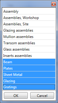
Here you specify whether the STEP data are also to be auto-generated. The default setting is No. If you set the parameter to Yes, you can select the part types to be considered for the STEP export from a selection window that you open in the Collect part types for STEP export row:
|
|
Article attributes for CAM documents |
Here you determine which article attributes are to be assigned to the CAM document attributes when the CAM data are created. To transfer article attributes of the semi-finished product to CAM document attributes, click on the Article attribute;Document attribute For instance, if you want to assign the article attribute DESIGNATION of the semi-finished product to the CAM document attribute COMMENT, you must do it like this:
|
|
Automatic CAM data export |
If this parameter is set to Yes, the CAM data are automatically exported from HELiOS to the Windows file system to the folder specified at Windows export path when creating/updating the CAM data. Depending on the file type, the files are stored in a separate sub-folder, e.g:
The files are automatically named according to the configuration file BIM_PDM_CAMExport.ftd (in the HiCAD sys directory). Default setting is the part attribute Item number. The default setting for automatic CAM data export is No. Important:
|
|
Windows export path |
Here you specify the path for automatic CAM data export. |
 Important:
 > Sheets
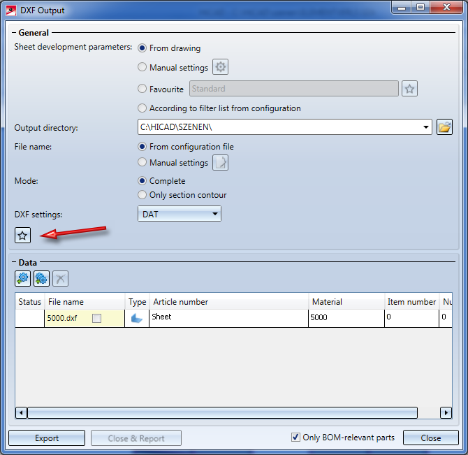
 button and define the desired assignments. Each assignment must be written in one line, as shown below.
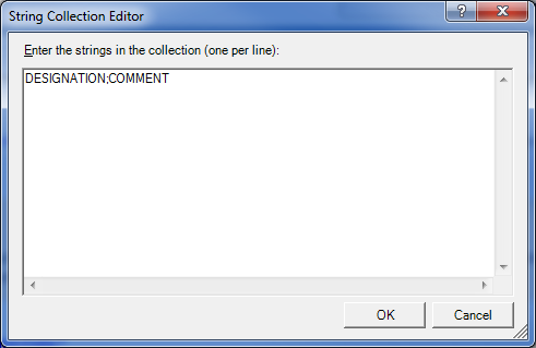
 Example 3: Create / Manage Production Data
External documents, general
In practice, it often happens that overview drawings of a model drawing are created manually in a separate sheet area. These drawings contain, for example, sectional views, cut-outs, shortened views, detail views, etc., and are intended to illustrate how the model is realized. These sheet areas are not taken into account when creating external production documents. In order to be able to manage these documents together with the corresponding model in HELiOS, HiCAD offers the possibility to automatically create a PDF, DXF and/or DWG file of the respectively active model or sheet area directly when saving a model drawing.
- List of manual document types for external documents
The document attribute DOKUART defines for which documents external documents are to be created automatically when saving the model drawing. Click on the  symbol and then enter the desired document types. Each document type must be in a separate line, for example:
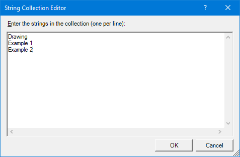
For example, this list would have the effect that for all documents with the document type (attribute DOKUART) Drawing, Example 1 and Example 2, external documents can be created automatically.
- List of document attributes to be transferred
Here you determine which document attributes are transferred to the external files. To do this, click on the symbol and then enter the desired attributes, whereby each attribute must be written in a separate line
The attributes listed in the figure are pre-set. You can change this list individually.

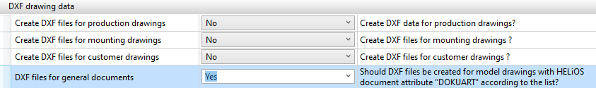
To enable the automatic creation of documents for the document types listed above, you must set the desired parameters to Yes at DXF drawing data:
If all parameters are set as desired in the Configuration Editor, the next time HiCAD is started with Management + BIM, the following procedure is carried out:
- When saving the model drawing, the system checks whether the document type of the model drawing exists in the list contained in the Configuration Editor.
- If this is the case, not only the model drawing is saved, but also the active model or sheet area is created as a PDF, DXF and/or DWG file.
- The created files are assigned to the same project as the model drawing and stored there - depending on the format - in a sub-folder (e.g. PDF or DXF).
- The created files are assigned the drawing number of the model drawing.
Further information can be found here.
External drawing data
Here you specify whether DXF, DWG or PDF files of the production drawings are also to be auto-generated. Possible settings are as follows:
- No,
- Upon Checkup and Release,
- Upon creation and update, or
- Upon Release
Default setting is No.
Similar to the external part data, drawing data can also be automatically exported from HELiOS to the Windows file system. For this purpose, the parameters
- Automatic drawing data export and
- Windows export path
are available. Depending on the file type, the files are stored in a separate sub-folder, e.g:

The files are automatically named according to the configuration file BIM_PDM_WSDExport.ftd (im HiCAD sys-Verzeichnis). The default setting for the designation is:
Article master attribute COMPONENT_DRAWINGNUMBERTEXT Part attribute Item number.
Important:
The files exported to the Windows file system are not managed in HELiOS.
 If you select Upon Checkup and Release or Upon Release, the files will already be entered upon creation and update into the database as Empty documents.
With the parameters PDF-/DXF-/DWG files for general documents you specify whether PDF/DXF and/or DWG files of the active sheet area are automatically created when saving a model drawing with the document type listed under List of manual document types for external documents.
Postprocessor for PDF creation
When creating a PDF, a Postscript file is first created - as with the HiCAD Spooler - and then converted into the PDF format. The following prerequisites must be fulfilled for this:
- The HiCAD Postscript printer driver (ISD File Printer) is installed. You can find this driver on the HiCAD installation DVD. To install the driver, insert the DVD and select the option Postscript Printer under Client Installations.
- A corresponding postprocessor for converting Postscript into PDF format must be available, e.g. Ghostscript. This is not supplied by I! This postprocessor must be entered in Configuration Editor at PDM > Management + BIM, for example:
C:\Program Files\gs\gs9.05\bin\gswin64c -dNOPAUSE -dBATCH -dPDFA -sDEVICE="pdfwrite" -sOutputFile="<FilePath><FileName>.pdf" <CurrentFile>

Requirements for a Smooth Operation (ManBIM) • Management + BIM Settings in the Configuration Editor (ManBIM) • Important Information(ManBIM)