Plant Engineering - What's New?

Service Pack 2 2020 (V 2502)
Classify pipeline article
If you select the creation of an article master when generating isometrics or piping plans, the article master in HELiOS is assigned the new classification Pipeline as of HiCAD 2020 SP2. However, this only applies to articles that you generate as of HiCAD 2020 SP2.
For the classification Pipeline, a corresponding input mask and the new HELiOS attribute PIPE_CLASS_NAME for the pipe class name are available in HELiOS.

To use the new mask and the new attribute you must first update HELiOS using the tool DbplantDataImport.exe and then restart HiCAD.
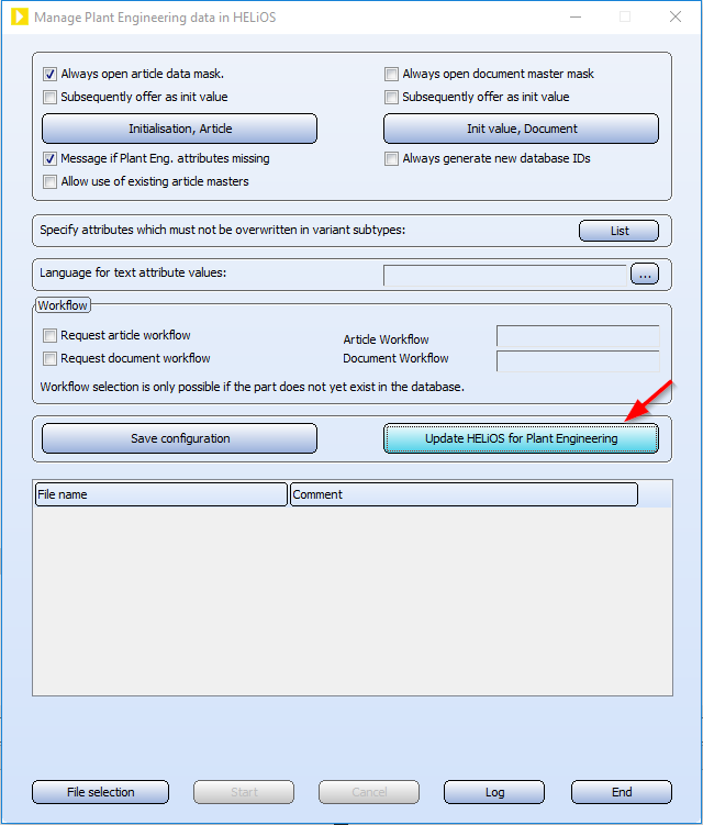
Automatic transfer of the pipeline attributes
The attributes of a pipeline can also be automatically transferred from HiCAD to HELiOS when saving. To do this, proceed as follows:
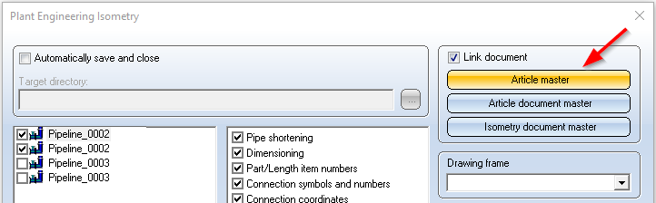
- On the HELiOS PDM Ribbon tab at Others > Link
 > ..., select the function Article master sync when saving
 . Specify the assignments shown there.
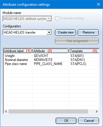
(1) Attribute, (2) Target attribute, (3) Creation scheme
End the function with OK.
- Since the assignments only become effective after a restart, close HiCAD.
- In the Configuration Editor at System settings > HELiOS, activate the Transfer part attributes to HELiOS checkbox.
- The next time you start HiCAD, the settings you made previously will apply.
Please note:
If you want to subsequently assign the classification Pipeline to existing articles, you must change this manually. To do this, click on the Classification  symbol in the dialogue window for the respective article and then activate the Pipeline checkbox at Plant engineering in the Classification dialogue window. You can then assign/change the attributes Nominal diameter, Weight and Pipe class name.
Move pipe parts
At Plant Engineering > Part Tools > Copy > ... you can find the new Move pipe parts  function.
This function works similar to copying of parts. The difference is that here straight pipes are not moved and the parts to be moved must form a straight string. In addition, after moving parts, an attempt is made here to fill the gap with straight pipes.
Before you call the function, you must first select the parts to be moved. This can be done either manually or with the Select part chain function. The selection of the parts to be moved may contain straight pipes, but they are not moved with them.
After calling the function, HiCAD prompts you to select a so-called handle for moving the part. This is the point over which the move is placed in the drawing. The allowed attachment points are highlighted in colour in the drawing.
If you have selected the handle, all parts lying on a dashed line running through this point will be attached to the cursor. Then, determine the target point of the move. If necessary, a dynamic route change is automatically carried out at the target point to make room for the moved parts.
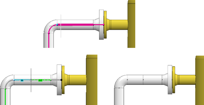
An example:
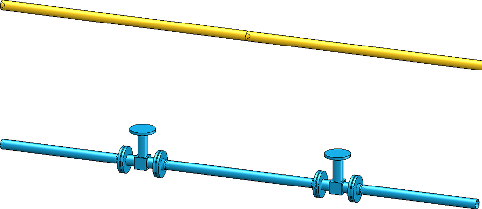
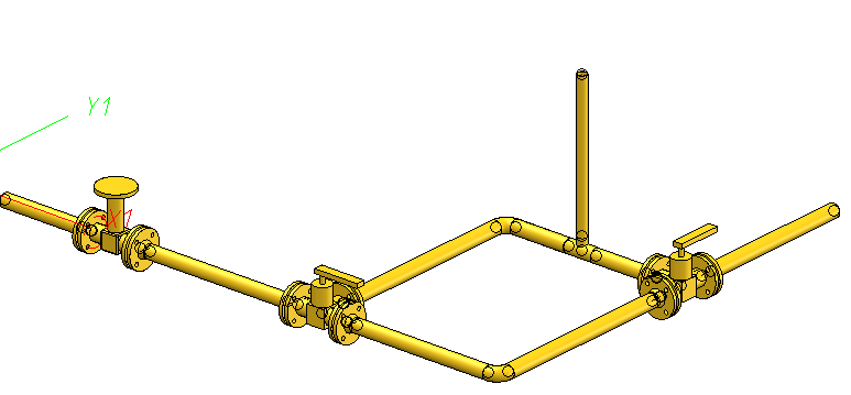
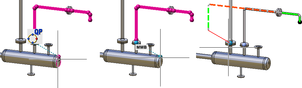
Let's take a look at the drawing shown below. The two valves are to be moved to the upper pipeline.
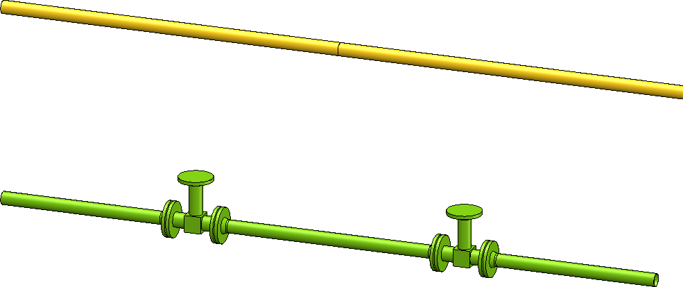
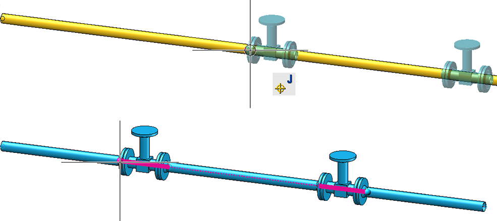
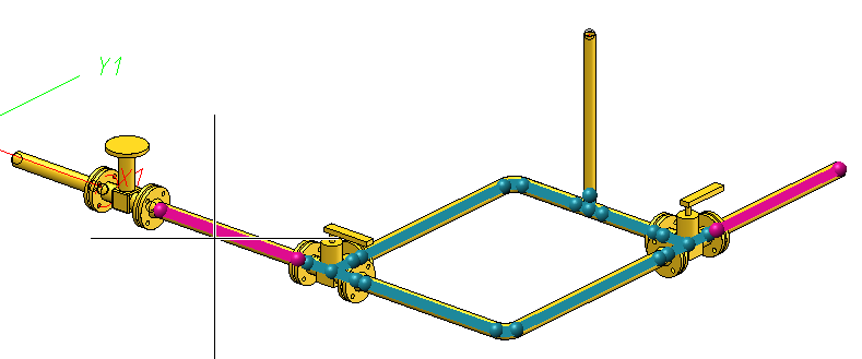
Select the desired part chain. Alternatively one could also select the two valves manually, which, however, would take more mouse clicks.
The possible handles of the part are highlighted. Select a handle and specify the target point for the displacement.
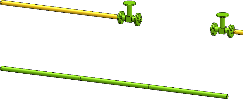
Result:
Combined BOM / length list
When generating bills of materials, the lengths of similar straight pipes can be combined. The Combine pipe length lists in BOMs checkbox is available in the Configuration Editor at Plant Engineering > Bills of materials.
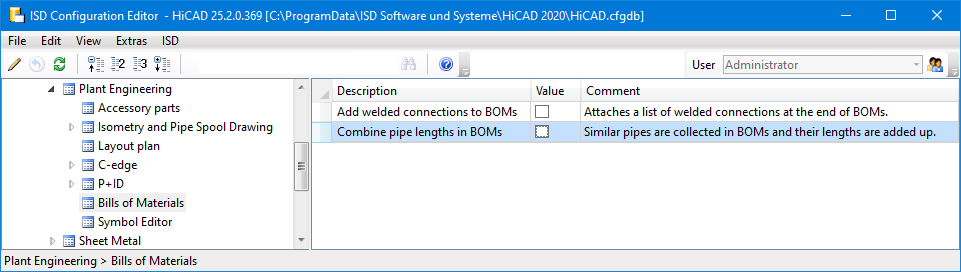
If the checkbox is active, similar pipes are combined to a single pipe when generating bills of materials. The length of this pipe is equal to the sum of the individual pipe lengths. By default, the checkbox is inactive.
The following figure shows a construction with three pipelines - one main pipe (red) and two secondary pipes (green).
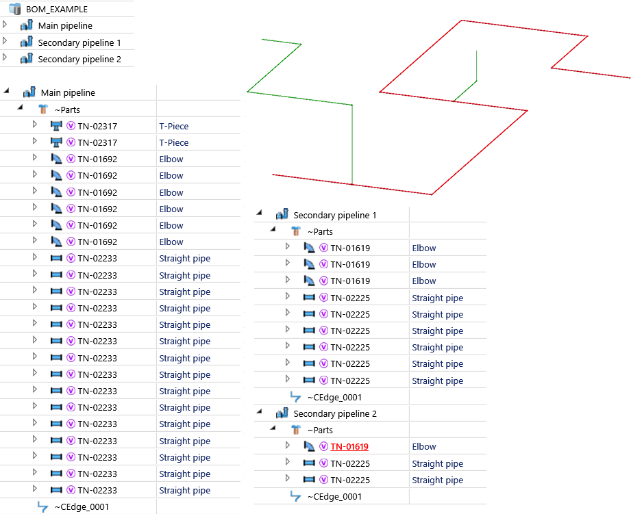
The BOM has been created for this model drawing - with and without a summary of the pipe lengths.
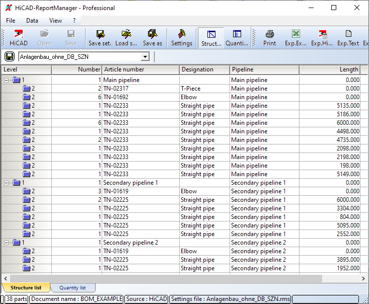
BOM without summary of pipe lengths
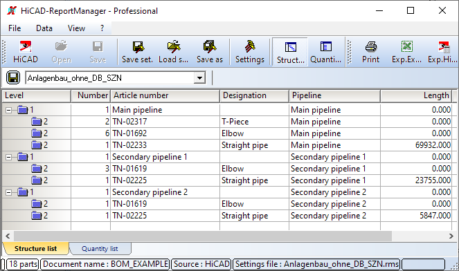
BOM with summary of pipe lengths
![]() Please note:
Please note:
- Except for the length and weight of the pipe, the remaining pipe attributes of a single pipe in the summary are used. These are usually the attributes of the first pipe (in the part structure) of the combination.
- Pipes are combined according to their structure in the structure list. This may differ from the pipeline structure, for example, if pipelines are not marked as BOM-relevant.
Calculate weight of pipeline
Weights of pipe parts of a pipeline are summed up from SP2 and transferred to the corresponding pipeline. For the calculation of the weights, pipelines are treated in the same way as assemblies. This means in particular
- Only weights of parts that are BOM-relevant are totalled.
- The weight of a pipe part is multiplied by the entry in field Qty. per part. An empty field is equivalent to the value 0.
- The pipeline must also be BOM-relevant for the weight to be entered.
- The weight of accessory sets is not taken into account.
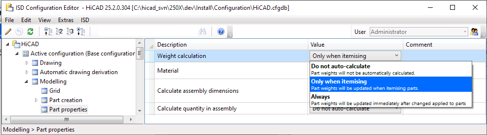
When the weight calculation of assemblies and thus also of pipelines is performed can be changed in the Configuration Editor under Modelling > Part properties > Weight calculation. The ISD default setting is Only when itemising.
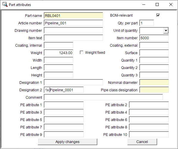
The attribute mask for pipelines has also been extended by the Weight fixed checkbox. If this is active, the entered weight is not overwritten during a weight calculation. The checkbox is inactive by default.
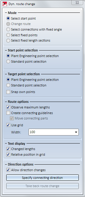
Dynamic route change
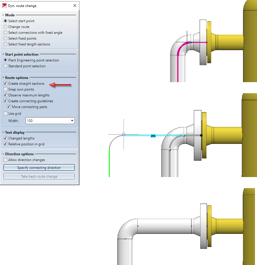
Create straight sections
Previously, it was only possible to change the lengths of existing pipes with the dynamic route change. In many cases, however, it is desirable to be able to create additional straight sections by changing the route. This is possible from HiCAD 2502 on. For this purpose the dialogue of the function has been extended by the checkbox Create straight sections.
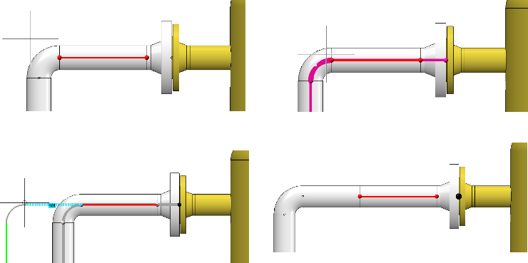
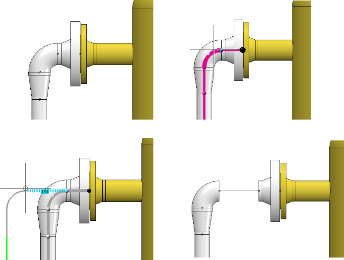
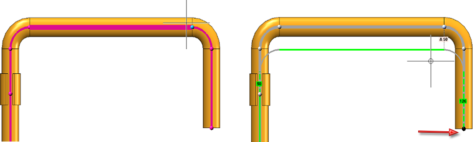
A typical use case is the increase of the distance between two parts, such as the illustrated elbow and the flange.
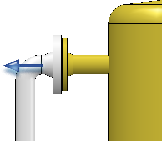
At this point you can reach your target as follows:
Simply pull the elbow away from the flange. A piece of straight pipe appears between the elbow and the flange. Please note that it is important to know on which side of a connection the cursor is located when selecting the connection.
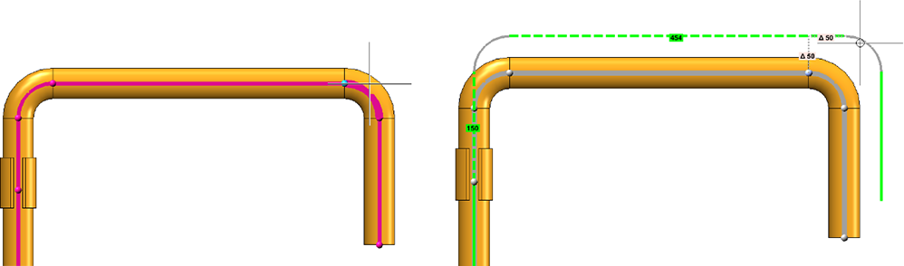
We select the connection at the elbow once more. Note the different results depending on which side the connection is selected from.
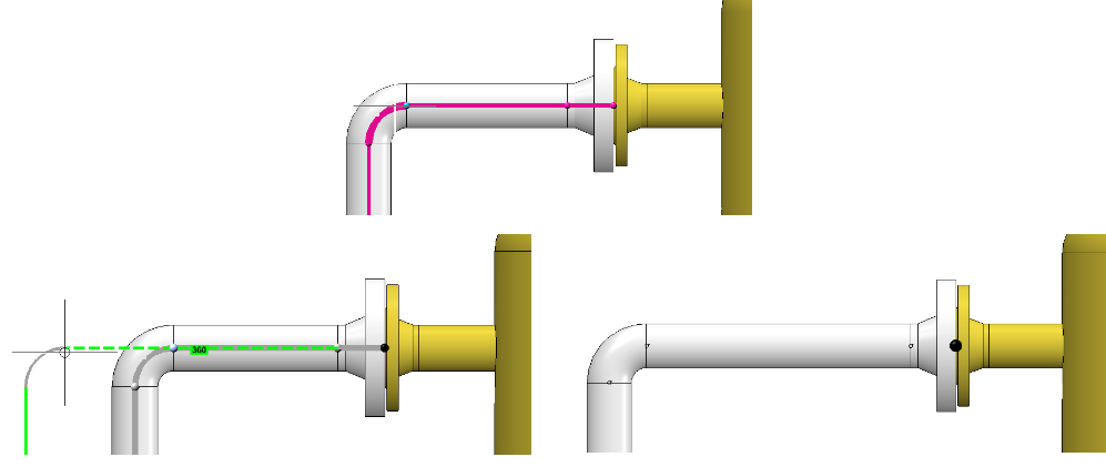
Elbow side
Pipe side
If you pull the elbow again, the previously created straight pipe will be extended. If, on the other hand, you drag the straight pipe, a new straight section is created between the straight pipe and the elbow.
In general, dragging on a connection causes a new straight section to be created. Unless a straight pipe follows which may be changed in its length. Then its length is increased until its maximum length is reached. From then on a new straight section is created. If you had fixed the length of this straight pipe, the behaviour would be the same as that of a straight pipe whose maximum length has been reached, i.e:
If you push a connection, no new straight sections are created there. However, a new straight section can be created at another location if the target position would otherwise not be reachable, which was forced by the length-fixed section in the following:
The newly created straight pipe is created as a modified copy of an already existing straight pipe. The existing straight pipes within the same pipeline are used to determine the straight pipe to be copied. If one is found that matches the connection conditions, a length-adjusted copy of this pipe is installed. If such a pipe is not found, a leading edge pull section is inserted instead. In the following example a straight pipe with a nominal diameter of 50 is required, but after the reduction only pipes with a nominal diameter of 32 follow:
|
Limitations:
|
Select target point
Until now, there were two methods of target point selection in the route change:
- Plant Engineering point selection
Automatic recognition of the connecting points and adoption of the connection direction for directional adjustments
- Standard point selection
Common HiCAD point selection with all available point options - but without automatic recognition of the connection directions.
From SP2 on, there is only one point selection, which basically corresponds to the usual HiCAD point selection. However, points named here will also be checked to see if they are Plant Engineering connection points. For such points, the connection direction is still determined and the option Snap own points in the dialogue window of the route change is effective.
Another new feature is that the target point can always be selected with the left mouse button.
Select fixed point
The pre-selection of fixed points in the route change has been revised. It now depends on the side of the connection where the cursor is located when selecting the point to be moved.
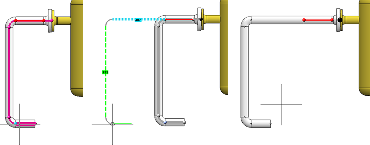
A common application of the route change is to move the end of a pipeline without directly grabbing the end point. Until now, in such a case the free ends of the pipeline were provided with fixed points, which had to be removed manually:
From SP2 on, no more fixed points are set at those free ends of the pipeline that follow on the side of the cursor.
Case 1: Selection of the start point on the pipe side.
A fixed point is displayed.
Case 2: Selection of the start point on the sheet side
No fixed point is displayed (if there is a connected component at the end of the pipeline, a fixed point is of route created there).
Minimum pressure of pipe parts
Since HiCAD 2020 SP1, the pressure range has been a search criterion for all component types (except weld seam gaps). In this context, the HELiOS attributes and masks for the classification of components in Plant Engineering have now been adapted in such a way that a pressure range can be defined.
- The previous attribute DRUCK (Pressure) describes the maximum nominal pressure.
- The DRUCK_MIN (Min. pressure) attribute for the minimum pressure is new.
Service Pack 1 2020 (V 2501)
Part Tools
Modified Ribbons and Pull-down menus
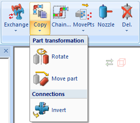
The Part Tools function group now contains two new functions:
 Copy pipe parts and
In this context the functions
have been moved to the PullDown menu of the Copy parts function,; also the former Move+Rotate part function has been renamed to Move part.
Select part chain
The new Select part chain  function allows you to select complete part chains. To do this, you first select two pipe parts which serve as start and/or end points of the part chain. HiCAD then selects all parts which are located on a connection between the start and end of the chain.
A preview is displayed while selecting a chain. Start and end of the chain are displayed magenta (Special colour: Marking 1) and the additional parts of the chain are displayed blue (Special colour: Marking 3).
Copy parts
With the new Copy parts function you can copy a selection of pipe parts into a pipeline. Parts from several pipelines can be copied into a single target pipeline. Source and target pipeline can also be identical.
Before you call the function, you must select the parts to be copied - either in the ICN or in the model drawing. The part to be copied will then either be the active part or the active part list. You can also use the Select part chain function to select the parts.
The copying of parts is done in several steps:
- Select handle
First you define the handle, i.e. the point via which the copy will be placed in the model drawing. You can select all free connecting points of the part list.
- Select target point
Here the position is selected where the parts to be copied are to be insterted. A preview of the parts to be copied is displayed at the current cursor position. Three different types of target points are possible.
- Copy onto a connection point
- Copy onto a guideline
- Copy onto a free point
After determining the target point, it may be necessary to perform a dynamic route change - for example, if a connection between two parts has been selected. HiCAD attempts to determine the target of the route change itself.
- Select target pipeline
From the selection in the second step, it is not always clear to which pipeline the parts are to be copied (e.g. when connecting to a component or copying between two pipelines). In this case the target pipeline must be selected.
In the example below, the highlighted blue parts (1) have been copied into the yellow pipeline.
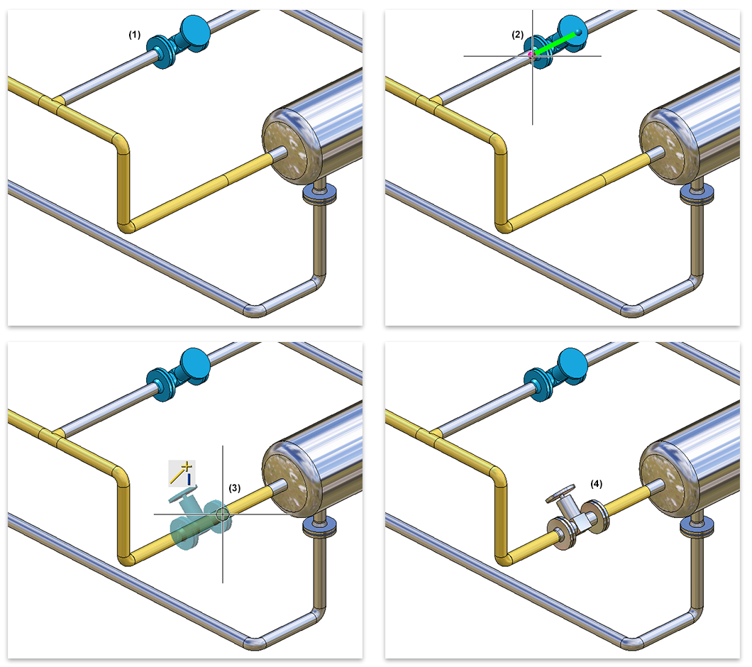
(1) Part selection, (2) Selected connecting point, (3) Target point determination, (4) Result
Plant Engineering Settings
Part search
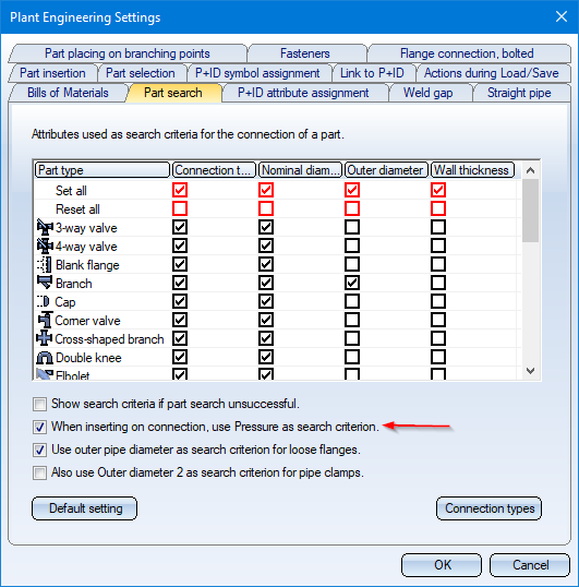
Previously, a pressure range was only used as a search criterion when searching for seals. As of HiCAD 2020 SP1, the Pressure range is a search criterion for all part types (except for weld seam gaps). On the Part search tab in the Plant Engineering Settings dialogue window the checkbox Use Pressure as search criterion for flange connections has therefore been renamed to When inserting on connection, use Pressure as search criterion.
If a part is to be connected to another part, then - if this option has been set and a value for the Pressure attribute has been assigned to the other part - this pressure is used as search criterion when searching for the part to be connected.
Isometry and Pipe plan
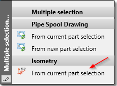
Multiple selection when starting the isometry
If you have selected several pipe parts or pipelines in the model drawing, then the isometry can also be started from HiCAD 2020 SP1 via the Multiple selection context menu. To do this, right-click after your multiple selection and choose Isometry - From current part selection in the context menu.
In the Plant Engineering Isometry dialogue window, the checkboxes of all pipelines belonging to the selection will then be active or all pipelines to which the parts of the multiple selection belong.
Parts
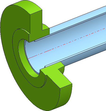
Insert loose flange as regular flange
Loose flanges can be inserted as regular flanges from SP1 onwards. The loose flange is pushed down from the straight pipe by a fixed excess length. This value can be set in the Configuration Editor at Plant Engineering > Layout plan > Insert loose flange as with excess length.
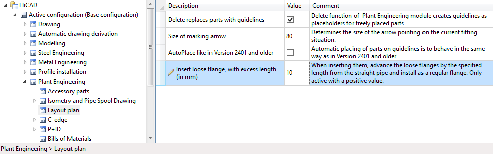
If you enter a value of 0 or a negative value, loose flanges will be installed as usual. If a positive value is entered, then each loose flange is installed like a regular flange.
In particular, when connecting to a straight pipe, it is not necessary to connect with the first point as usual for loose flanges, but with the second point.
The default setting is 0.
Insert placeholder
As of HiCAD 2020 SP1 it is possible to insert placeholder valves in a pipeline. The new function

has been made available for this purpose.
is available for this purpose.
In this way, useful valves can be inserted in the planning process even if the actual valve has not yet been determined or is not yet available. The placeholders ensure that meaningful BOMs and isometries can also be created in the planning phase.
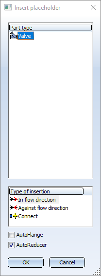
The insertion of a placeholder valve is identical to the insertion of a regular Valve. The only difference is that the part is not selected via HELiOS or the HiCAD catalogue. Instead, a dialogue window is displayed in which various nominal diameters can be selected under Sub-types.
After calling the function, the nominal diameter that best matches the nominal diameter of the selected pipeline is automatically selected here.
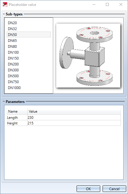
For each nominal diameter, the values for the length and height of the valve are preset in the Parameters area. These values can be adjusted individually.
Placeholder valves automatically receive the article number Placeholder valve and the corresponding names.
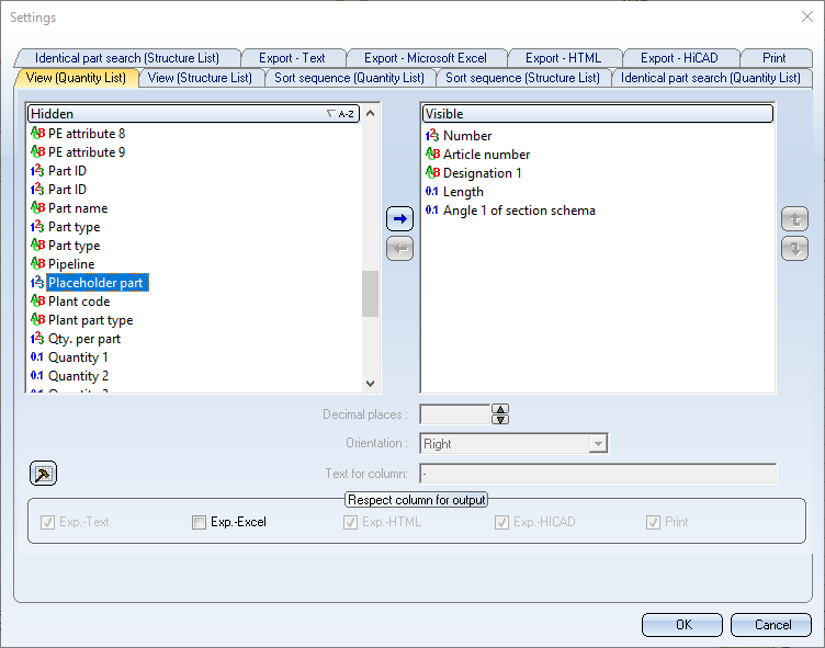
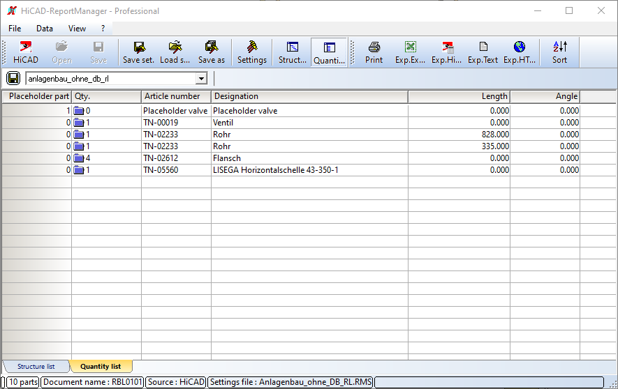
To make it clear in BOMs which valves are only placeholders, the BOM attribute Placeholder part is available for Plant Engineering BOMs. If this attribute has the value 1, then the part is a placeholder.
In the example shown below, the Quantity List in the Report Manager has been extended by the column Placeholder part.
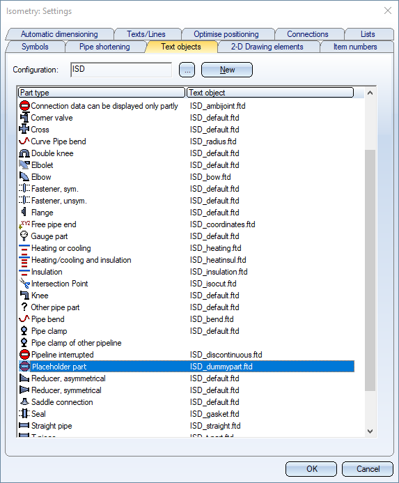
In the isometry, placeholder valves are shown as red dashed lines and have a designation tag with the text Placeholder.
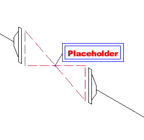
The designation tag can be customized in the isometric settings on the Text objects tab if desired.
Directly insert classified .KRA files
When components are installed, KRA files that are classified as components in HELiOS can now also be installed directly.
An example:
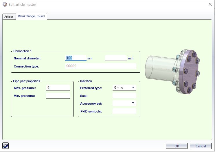
The displayed component is to be classified as a component of type Vessel. For this purpose, an article master is first assigned and then - before leaving the dialogue window - the button Classification is clicked.
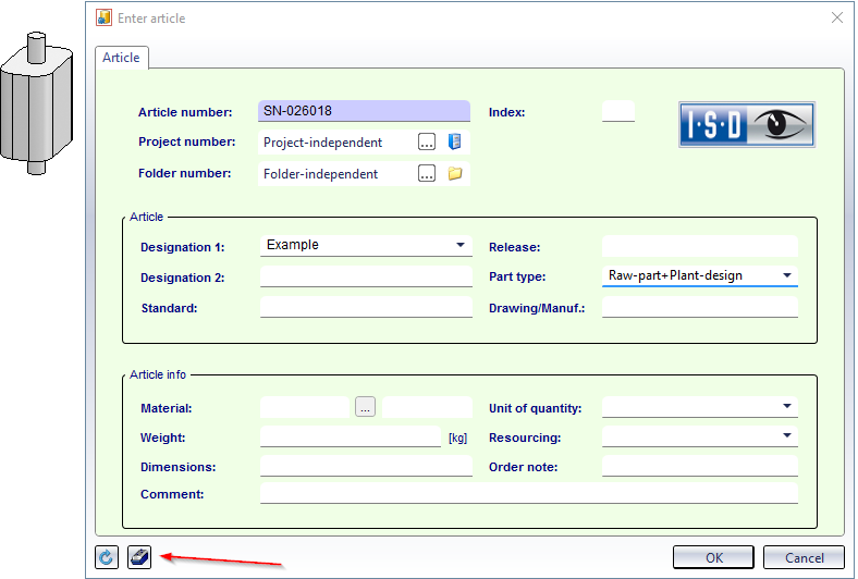 .
.
After selecting the component type, the vessel data can be specified.
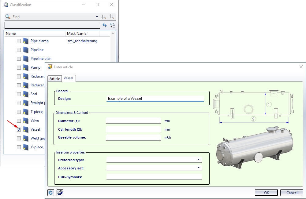
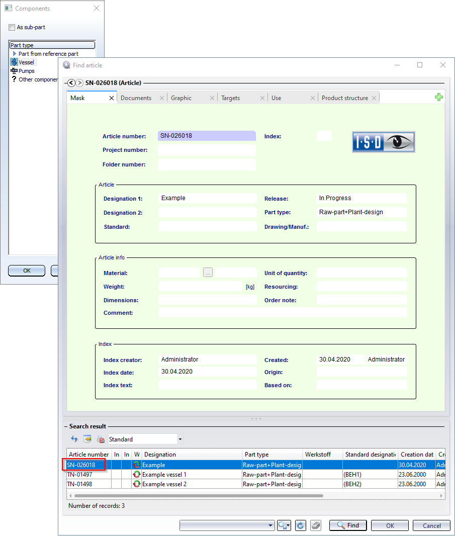
If the entry Vessel is now selected when installing a component, the KRA file saved above is available.
Pipeline Tools
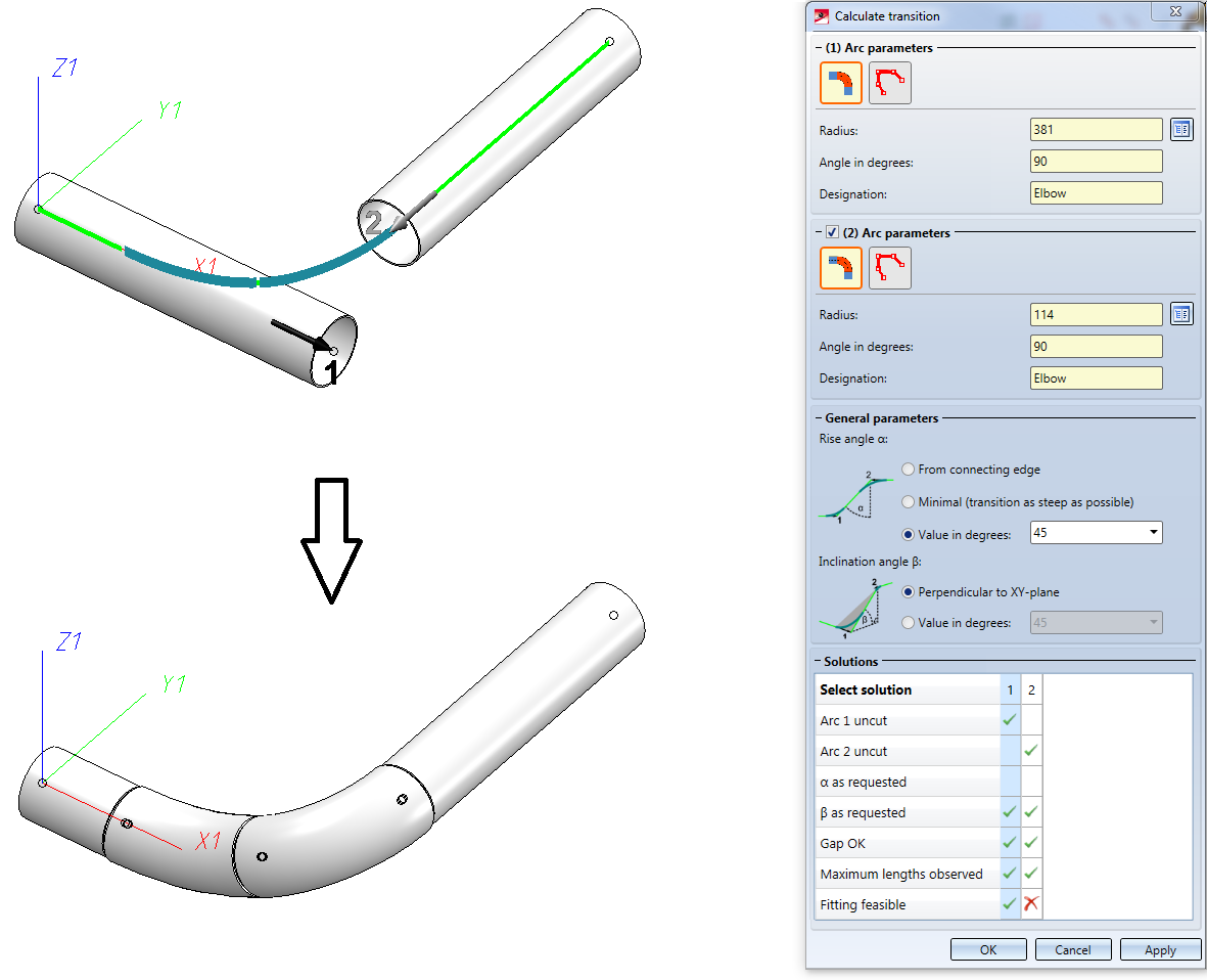
Calculate transition: Improved dialogue
The dialogue of the Calculate transition  function has been improved:
- Additional information about the selected elbows is now displayed: Nominal diameter, Outer diameter and Wall thickness. Furthermore, the Designation field has been enlarged.

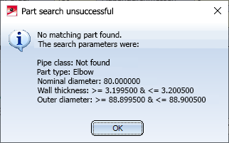
- If the part search fails, a corresponding message is displayed. The part search uses as search parameters values from the selected connections, namely those that you have defined for Elbows on the Part search tab of the Plant Engineering Settings dialogue window. The pipe class is also taken into account. If no suitable part is found, a corresponding message is displayed:
Major Release 2020 (V 2500)
Restructured Ribbon and context menus
- The AutoRoute guideline and AutoPlace parts
 function can now be found in the pull-down menu of the AutoPlace parts on guidelines
  function.
 - The Set Plant Engineering ID
 function has been moved to the pull-down menu of the Plant Engineering Settings.
 - The previous functions for the editing of pipelines have been divided into 2 groups:
- Functions that change the structure of pipelines can be found at Plant Engineering > Pipeline Tools > Change > ... .
- Functions that change the properties of pipelines can be found at Plant Engineering > Pipeline Tools > Assign >....
- The functions of the Check menu can now be found in the pull-down menu of the Collision check function at Plant Engineering > Pipeline Tools > Coll.. >....
Pipelines
Activate pipeline
As of HiCAD 2020, the active pipeline is determined via the active part. This means: If the active part belongs to a pipeline, then this pipeline is considered the active pipeline. Otherwise, no pipeline is active. The previous functions for activating pipelines are therefore no longer available from HiCAD 2020 onwards.
Change pipeline route
Previously, only Plant Engineering connecting points were permitted as start points for route changes. As of HiCAD 2020, any points can be selected, i.e. also points that were determined via point options.
- In the Plant Engineering point selection mode, the route change behaves as before.
- In the Standard point selection mode, you can select any point as the start point. In order to be able to clearly define the sections of the pipeline to be changed, the route change must nevertheless refer to a Plant Engineering connecting point. Therefore, HiCAD automatically suggests a Plant Engineering connecting near the selected point after the selection of the start point. This is indicated by with a MMB note.
- If you want to use the suggested point, just click the middle mouse button.
- Otherwise, simply select another Plant Engineering connecting point with a left-click.
During the route change, an auxiliary line is drawn between the selected start point and the Plant Engineering connecting point. This auxiliary line is displayed in red (Special colour X-axis) if the starting point cannot reach the target point.
Examples of the Standard point selection can be found here.
Settings
Set Local CS
The setting of a local coordinate system has been simplified in HiCAD 2020. The selection of the direction of the coordinate system no longer takes place when starting the function, but can be set, after a right-click, via the respective context menu. In addition, HiCAD now displays a preview of the coordinate system.
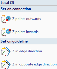
Left: Up to HiCAD 2019 Right: As of HiCAD 2020
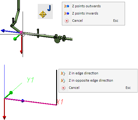
Preview and context menus
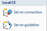
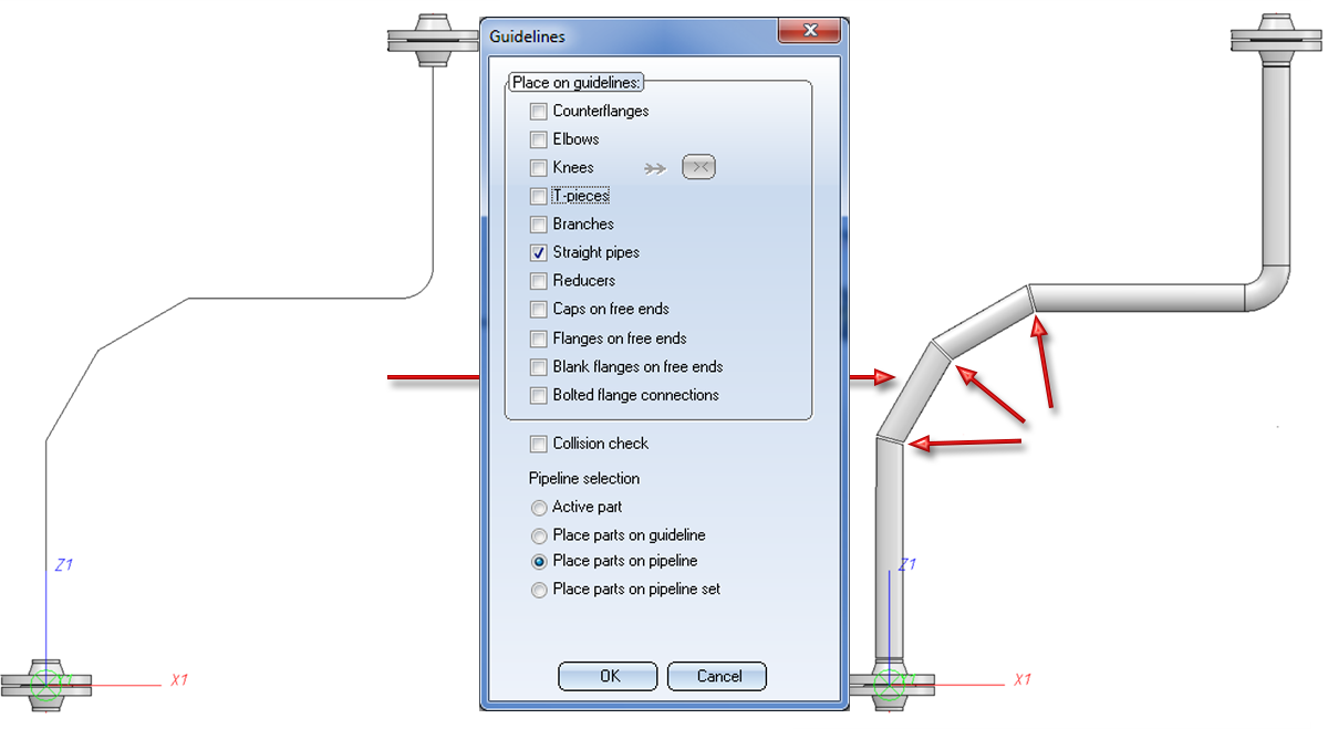
Guidelines
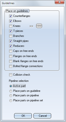
Pipeline selection for automatic placing of parts
The selection of the active pipeline for the automatic placing of parts on guidelines has been revised. New here is the Active part option. Here the pipeline to be assigned is determined via the active part. If the active part is a guideline, parts will be placed only on this guideline. Otherwise the parts will be placed on the superordinate pipeline. If the active part has no superordinate pipeline, the dialogue behaves as with the Place parts on pipeline option.
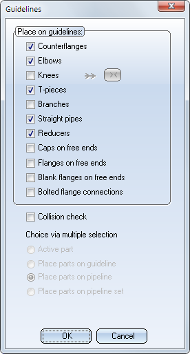
In addition, the automatic part placing also supports multiple selections from HiCAD 2020 onwards. If several parts are selected, of which at least one is a sub-part of a pipeline, the options are greyed out and the elements to be assigned are determined via the multiple selection. Analogous to the selection via the active part, parts will be placed on individual guidelines. For each other selected part, parts will be placed on the respective superordinate pipeline.
Mitre cuts during automatic placing of parts
If you select neither elbows nor knees, but straight pipes, mitre cuts will be applied to the straight pipes:
Parts - New automatisms for parts
From HiCAD 2020 onwards, two new functions for part automatisms are available in the pull-down menu of the Change function (Plant Engineering > Pipeline Tools > Change > ...):
Calculate transitions and
 Edit arcs
Calculate transitions
Until now, HiCAD did not provide a simple way to calculate and place arcs for offset transitions. The problem here consists in connecting two pipelines using suitably cut bends, as in the following example:
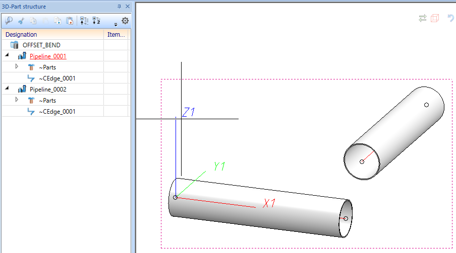
From HiCAD 2020 onwards, this problem can be solved with the new Calculate transition function:
Edit arcs for bent pipes
With this Editor you can modify arcs in Plant Engineering. You can change arcs for bent pipes, insert segment arcs and perform mitre cuts. The Editor requires a working with guidelines and can also modify unoccupied guideline edges.
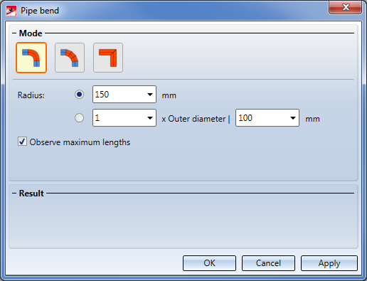
Three modes are supported:
|
|
Transition by bending |
|
|
Transition by segments |
|
|
Transition by mitre cut |


Delete counter-flanges
When deleting valves, counter-flanges in the same pipeline are now also deleted.
