Configuration Editor: Settings for Interfaces
In the ISD Configuration Management under Interfaces, you can define which default settings are to apply to the import and export of the general 3-D interfaces such as Step, IGES, DXF/DWG, etc. These settings are then displayed as default in the respective import/export dialogue when called up in HiCAD.
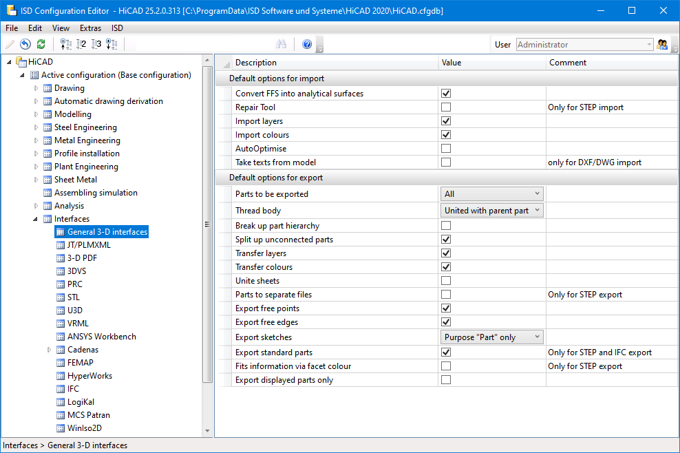
Not all settings are available for every interface.

Default settings for the import
For all file formats in the HiCAD dialogue Drawing > New/Open > Open  > 3-D Import, the settings made in the dialogue can be saved and loaded as favourites. To do this, click on the
  symbol in the dialogue. You can find more information on managing favourites in the Manage Favourites topic of the HiCAD Basics help.
You can specify which favourite is used as the default in the import dialogue in the Configuration Editor at Interfaces > Import.
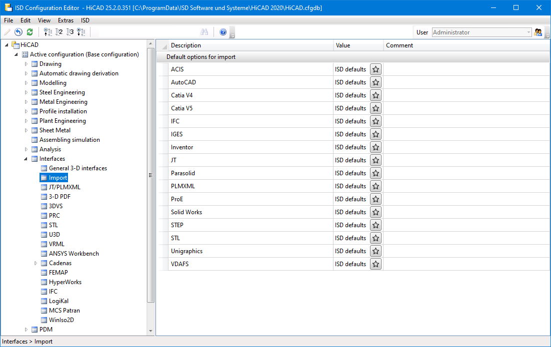
To preset a favourite for a file format, click on the symbol and then select the desired favourite.
When starting the Import dialogue, please note that the last selected settings are used as default for the respective file format. If you have not made any changes to the settings of the favourite defined in the configuration management, the favourite settings will be used.
ISD default settings
|
Setting |
Effect |
Default setting |
|---|---|---|
|
Convert FFS into analytical surfaces |
If this checkbox is active, free-form surfaces are automatically converted into analytical surfaces. If you do not want this, then deactivate the checkbox. This may be useful for sheet metal parts. |
active |
|
Repair Tool* |
If this checkbox is active, extended correction and repair functions are automatically executed during import, which ensure a better import of "bad" STEP files. The RepairTool is a separately licensable module. If there is no valid license, the checkbox is grayed out. If necessary, you can also use your own configuration file for the RepairTool. The default system file is located in the directory of the HiCAD installation at ...\sys\CADfix\Default\Import\ and is called STEPRepair.cwc. |
inactive |
|
Import layers |
These checkboxes determine whether layers and colors are taken into account during import. These settings refer exclusively to the properties of the entire part. |
active |
|
Import colours |
active |
|
|
AutoOptimise |
If this checkbox is active , a union of (divided) edges and surfaces is carried out directly during the import (corresponds to the HiCAD function 3D-Standard > Tools > Surface > Further ... > Optimise part). |
inactive |
|
Take texts from model** |
Activate this option to transfer the annotations of the AutoCAD model to HiCAD dimensioning. The texts will be imported as part annotations with leader line. Before the import, their appearance can be influenced via the Annotation settings(3-D Dimensioning + Text > Leader > Settings - Change ) in the system file ...\sys\DXF_Importtext.ftd. |
inactive |
|
Separate parts *** |
If this checkbox is active, then individual parts are built in separately instead of as one solid body. |
inactive |
* only for STEP
**only for 3-D DXF/DWG
*** only for STL
 For IFC import, the Attribute mapping configuration can also be defined in the Configuration Editor at Interfaces > IFC.
Default settings for the export
|
Setting |
Effect |
||||||||||||
|---|---|---|---|---|---|---|---|---|---|---|---|---|---|
|
Parts to be exported |
Here, you determine whether the entire drawing or only the currently selected list is to be exported. |
||||||||||||
|
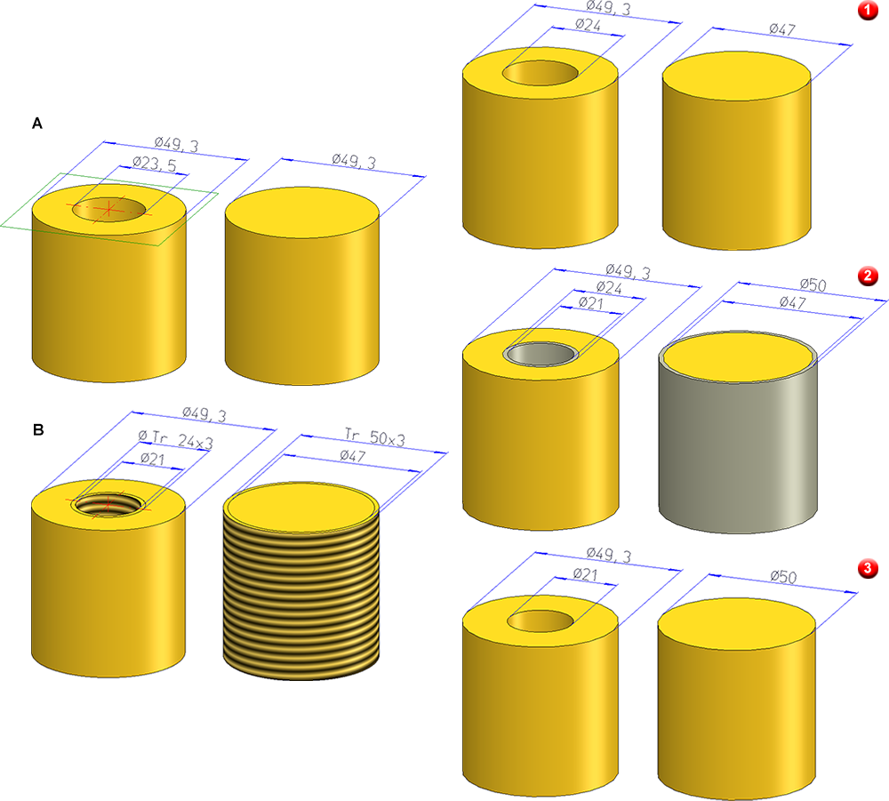
Thread body |
Thread bodies can be excluded from export, exported as separate parts, or exported combined with the superordinate part. Which diameters - of the corresponding thread table - are used depends on the selected setting and whether it is an internal or external thread.
DN = Nominal diameter, KERDI = Core diameter of internal thread The image below shows the example of a cylinder with diameter 49.3. A bore with diameter 23.5 was inserted in the left cylinder (A) and then a internal thread DIN 103, Tr 24x3. On the right, an external thread of type DIN 103 Tr 50x3 was inserted (B).
(1) Do not transfer |
||||||||||||
|
Break up part hierarchy |
If this checkbox is active, the part structure is broken up during export, i.e. all parts will be combined into one part. No Boolean operations will be performed in the process. |
||||||||||||
|
Split up unconnected parts |
If this checkbox is inactive, the hierarchy of parts without geometric relationship to each other will be broken up. If this option is active, the Break up part hierarchy checkbox should be deactivated. |
||||||||||||
|
Transfer layers Transfer colours |
Activate these checkboxes if layers and colours should also be taken into account during export. |
||||||||||||
|
Unite sheets |
Activate this checkbox if you want to unite all sub-parts of a sheet with its superordinate part, thus forming one part. |
||||||||||||
|
If this checkbox is activated, each part with a geometry is exported as a separate file. When exporting STL or VRML files, the file name is the name specified during export followed by a consecutive number. This does not apply to the export of STEP files. Please read the important information given in the STEP topic! If the Break up part hierarchy is active, no part files will be created! |
|||||||||||||
|
Export free points |
Here you define whether free points or edges should be taken into account during export or not. |
||||||||||||
|
Export free edges |
|||||||||||||
|
Export sketches |
Here you can select whether sketches are to be exported. You can exclude sketches completely from export (none), export all sketches, or export only sketches that have the purpose "Part". If sketches are to be exported, the checkboxes for free points and free edges should also be active. Otherwise a warning symbol appears. |
||||||||||||
|
Export standard parts** |
Here you specify whether standard parts (bolts, roller bearings, springs ...) are to be considered for export. |
||||||||||||
|
Here you can specify by activating or deactivating the checkbox whether fits information are to be transferred via the surface colour. On the exported part the diameter of the corresponding bore will be highlighted. For this, the option Transfer colours must be active. In the sys directory of your HiCAD installation you will find the configuration file fitinfo_color.dat, where the assigning of RGB colour values to fits data is specified. |
* only for STEP
![]() Please note:
Please note:
- Powder marking lines are exported automatically.
- Apart from General 3-D interfaces you can find the parameters for the default settings for the following interfaces:
- JT/PLMXML
- 3DPDF
- 3DVS
- PRC
- STL
- U3D
- VRML
- Ansys Workbench
- CADENAS
- FEMAP
- HyperWorks
- IFC
- LogiKal
- MSC Patran
- WinIso 2D
