You can additionally influence the behaviour of the production drawing generation via the Configuration Editor (ISDConfigEditor.exe in the HiCAD EXE directory). The relevant settings can be found at PDM > Management + BIM > Production drawings.

The following parameter settings are available:
Production drawings
- Update production drawings
- Production drawings for glasses
- Production drawing / processing notes for unprocessed beams
- Generate n-digit drawing number
- Drawing number generation
- Classify production drawing
- Drawing number always dependent on drawing type
- Show release status in title block
- Consider total number in production drawing
- Create HELiOS attributes from FTD file
- Create only one production drawing per part
- Output corresponding assembly drawing
- Transfer article attributes
- Article attributes for drawings with multiple parts
- Create sectional views when updating production drawings
- Rearrange views when updating production drawings
- Delete unused Sheet areas
Mounting drawings
General

Update production drawing
Via this parameter you can determine whether production drawings are to be loaded and updated upon Checkup and Release. The default setting is Yes.
Choosing No can make sense if only the Workflow status of an assembly, but not the content of the drawing is changed. When you choose this setting, the drawings will, for instance, not be loaded/updated if the Workflow status changes from Checkup to Released, or if the index changes.
Production drawings for glasses
When creating production drawings for glasses you distinguish between rectangular glass panes and modelled glass panes (i.e. non-rectangular and/or unprocessed glass panes).
If you set the parameter Production drawing for glasses to Yes, production drawings will be created both for rectangular panes and modelled panes. This is the default setting.
If you choose the setting Only for modelled glass panes instead, rectangular glasses will not be considered for production drawing creation.
Please note:
This parameter only applies to glass panes from the HiCAD catalogue, i.e. from the catalogues Factory standards > Glass panes and Factory standards > Multi-layered glass panes!
All other glass types, e.g. from LogiKal, are automatically considered modelled glass panes with production drawing.
Production drawing / processing notes for unprocessed beams
Depending on the corresponding feature entries, you distinguish between processed and unprocessed beams in your model drawing. For example, a lengthening, trimming, or moving points in a rectangle will not make the beam a "processed" beam. All other functions, e.g. as bores, subtractions, notches etc. on a beam will make the beam a "processed" beam.
Via the parameter Production drawing for unprocessed beams you can now specify whether "unprocessed" beams are to be considered for derived drawings or not.
The following settings are possible:
- Yes
Unprocessed beams will also be considered for derived drawings. This is the default setting. - No (cuts are no processings)
The HELiOS link No drawing required will be assigned to unprocessed beams when the model drawing is saved. This means that no drawings will be created for these beams. Cuts are not interpreted as processings, i.e. they will not be considered for derived drawings. - No (cuts are processings)
The HELiOS link No drawing required will be assigned to unprocessed beams when the model drawing is saved. This means that no drawings will be created for these beams. Cuts are interpreted as processings, i.e. they will be considered for derived drawings.
Handling of unprocessed beams depending on later machine processing
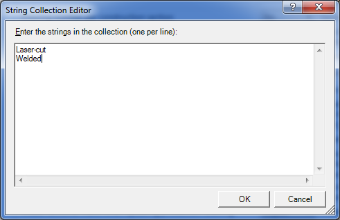
The drawing creation for unprocessed beams can also be controlled depending on later machine processings. For this purpose the HiCAD attribute Processing note $BHW is available. For instance, you can achieve via this attribute that a production drawing is created for unprocessed beams that need to be laser-cut, despite the current Production for unprocessed beams setting. For this to happen, the corresponding processing notes must be entered into the Collection Box of the Processing note for unprocessed beams parameter, e.g.:
The following additional adjustments are required:
- In the system files H_BHW.TXT (in the HiCAD sys directory) the processing notes must be added, too:

It is important that the spelling of the texts must be identical with those in the Collection Box (please also attention to case-sensitivity!).
- In the system files BRW_3DTeil_Profil.HDX and BRW_3DTeil_Profil_H.HDX (in the HiCAD sys directory) the attribute $BHW must be activated. If you have set the Parameter Configuration to Steel/Metal Engineering and Management + BIM, the corresponding definition has already been provided in the files; only the # character at the start of the entry needs to be deleted:

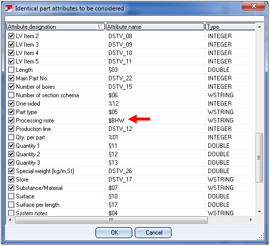
- The attribute $BHW must be made item-relevant. To do this, open the Management + BIM tab, choose Parts > Item...
 > ... with options
  and, in the dialogue window, click the Configuration button. In the displayed window, activate the attribute $BHW:
 Important note on Sheet Metal parts
One distinguishes between sheets with identical cross-sections (unprocessed sheets) and processed beams. If desired, you can suppress the output of sheets with identical cross-sections in the workshop drawing. To do this, go to Sheet Metal > Sheets with identical cross-sections in the Configuration Editor and activate the Suppress productions drawings for sheets with identical cross-sections... checkbox. The checkbox is deactivated by default. Click here for further information.
If you change this setting in the Configuration Editor, already itemized sheets need to be re-itemized and saved!
Generate n-digit drawing number
If you want an n-digit drawing number (padded with zeroes from the left) to be generated when creating production drawings, select the number of desired digits here. The n-digit drawing number will be assigned to the HELiOS document attribute DRAWINGNUMBER.
At the same time a text that is composed of the project name and the drawing number, separated by a "-" (e.g. EXAMPLEPROJECT-00005) will be assigned to the document attribute DRAWINGNUMBER_TEXT.
The default setting is 3-digit.
The parameter Drawing number generation can also be used to define whether numbering should be consecutive within a construction section, consecutive within a project, or project-comprehensive, or whether it should be switched off completely.
Similarly, you can select via the parameter Drawing number always dependent on drawing type whether the numbering is to be consecutive spanning both the production drawings and the mounting drawings, or separately for production drawings and mounting drawings.
The attribute DRAWING_NUMBER can also be configured individually if required. For this purpose the template file BIM_PDM_DrawingnumberGeneration.ftd is available that can be edited with the Templates, Attribute assignment function (Steel Engineering > Settings > ...).
Drawing number generation
If you have selected the generation of n-digit drawing numbers, you can use the parameter Drawing number generation from HiCAD 2020 SP1 onwards to specify how the numbering is to take place:
- By production sections (consecutively within one production section),
- By projects (consecutively within one project), or
- Project-comprehensive (spanning several projects).
Select None to deactivate numbering completely. The default setting is By projects.
Classify production drawing
Use this parameter to specify whether the value Production drawing is to be assigned to the HELiOS attribute Document type (DOKUART) in drawings created with the Management + BIM module (No) or if you want a distinguishing between detail drawing, assembly drawing, etc. (Yes). The default setting is Yes.
To ensure that the attribute DOKUART will be shown in the HELiOS masks and result lists you need to adjust them accordingly.
Drawing number always dependent on drawing type
If you have selected the Generation of n-digit drawing numbers you can determine here whether you want a consecutive numbering spanning all production drawings (assembly drawings, beam detail drawings, plate detail drawings,etc.) and mounting drawings (No), or prefer a separate numbering for production drawings and mounting drawings (Yes).
The default setting is No.
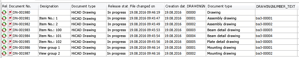
Example: Drawing number always dependent on drawing type = Yes
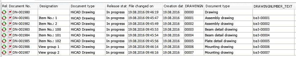
Example: Drawing number always dependent on drawing type = No
Show release status in title block
If you want non-released drawings to be marked in the title block, set this parameter to Yes. This is also the default setting. The title blocks of non-released drawings will be marked with an "in progress" note in the title block.
This marking requires the use of the _SZNATTRSTA attribute.
Consider total number in production drawing
Here you can specify whether the total number of parts is change relevant for the production drawing.
The default setting is Yes.
HELiOS attributes from FTD file
If you want to generate the HELiOS attributes BENENNUNG (Designation) and SACHNUMMER (Article number) for detail drawings from template files , set the parameter to Yes.
In this case, the attributes for assemblies, beams, general parts, Sheet Metal parts and Steel Engineering plates will be generated according to the corresponding template file.
|
Template file |
Settings for the |
Pre-setting |
|
BIM_PDM_WSD_Assembly_ArticleNumber.ftd |
Configuration of the HELiOS document attribute SACHNUMMER (Article number) for detail drawings of assemblies (assemblies with one main part) |
{Total quantity (Part attribute)} x {Article number (Part attribute)} |
|
BIM_PDM_WSD_Assembly_Designation.ftd |
Configuration of the HELiOS document attribute BENENNUNG (Designation) for detail drawings of assemblies (assemblies with one main part) |
%TS(TEXTE_STB401) {Item number (Part attribute)} %TS(TEXTE_STB401) stands for the content of the text key STB_401 which is the text Item No.: |
|
BIM_PDM_WSD_Beam_ArticleNumber.ftd |
Configuration of the HELiOS document attribute SACHNUMMER (Article number) for detail drawings of beams |
{Total quantity (Part attribute)} {Article number (Part attribute)} x{Länge (Part attribute)} |
|
BIM_PDM_WSD_Beam_Designation.ftd |
Configuration of the HELiOS document attribute BENENNUNG (Designation) for detail drawings of beams |
%TS(TEXTE_STB401) {Item number (Part attribute)} |
|
BIM_PDM_WSD_Multi_Designation.ftd |
Configuration of the HELiOS document attribute BENENNUNG (Designation) for detail drawings of multi-part beams |
%TS(TEXTE_STB401) |
|
BIM_PDM_WSD_Part_ArticleNumber.ftd |
Configuration of the HELiOS document attribute SACHNUMMER (Article number) for detail drawings of general parts |
{Total quantity (Part attribute)} x {Article number (Part attribute)} |
|
BIM_PDM_WSD_Part_Designation.ftd |
Configuration of the HELiOS document attribute BENENNUNG (Designation) for detail drawings of general parts |
%TS(TEXTE_STB401) {Item number (Part attribute)} |
|
BIM_PDM_WSD_SheetMetal_ArticleNumber.ftd |
Configuration of the HELiOS document attribute SACHNUMMER (Article number) for detail drawings of Sheet Metal parts |
{Total quantity (Part attribute)} x {Article number (Part attribute)} x{Length of 2-D development (Part attribute)} x{Width of 2-D development (Part attribute)} |
|
BIM_PDM_WSD_SheetMetal_Designation.ftd |
Configuration of the HELiOS document attribute BENENNUNG (Designation) for detail drawings of Sheet Metal parts |
%TS(TEXTE_STB401) {Item number (Part attribute)} |
|
BIM_PDM_WSD_SteelPlate_ArticleNumber.ftd |
Configuration of the HELiOS document attribute SACHNUMMER (Article number) for detail drawings of Steel Engineering plates |
{Total quantity (Part attribute)} x {Article number (Part attribute)} x{Length(Part attribute)} x{Width(Part attribute)} |
|
BIM_PDM_WSD_SteelPlate_Designation.ftd |
Configuration of the HELiOS document attribute BENENNUNG (Designation) for detail drawings of Steel Engineering plates |
%TS(TEXTE_STB401) {Item number (Part attribute)}
|
Use the Templates, Attribute assignment function (Steel Engineering > Settings > ...) to adjust the templates individually for attribute assignment.
Create only one production drawing per part
If you want only one production drawing to be created per part when performing a drawing derivation, set this parameter to Yes.
Output associated assembly drawing
When generating detail drawings, you can automatically transfer the document number of the assembly's single part as well as the assembly item number to the title block. For this to happen, you need to set the parameter Output corresponding assembly drawing to Yes (default setting is No.) In this case, the HiCAD drawing attribute SZNATTRAS will be assigned the corresponding assembly drawing name(s), the attribute _SZNATTRRRIN will be assigned the item number of the assembly, and will be displayed in the title block of the detail drawing.
A prerequisite for this is that a corresponding title block exists in which the drawing attribute _SZNATTRAS and _SZNATTRRRIN, respectively, can be displayed. The chapter Basics > Drawing Objects > Drawing Frame and Title Block explains in detail how to change title blocks and use variables in them.
 This only applies to detail drawings.
Transfer article attributes
When generating detail drawings with the Management + BIM functions you have the option to transfer article attributes of the semi-finished products to the document attributes of the detail drawings. Such document attributes can, for instance, be used in the HELiOS result lists as filters or search criteria.
To transfer article attributes of the semi-finished product to the document attributes of the detail drawing, click on the  icon and define the desired assignments. Each assignment is defined in one row and is composed like this:
Article attribute;Document attribute
If, for instance, you want to assign the Artcle attribute BENENNUNG (Designation) to the Document attribute BEMERKUNG (Comment) of the detail drawing, the assignment must look like this:
Article attributes for drawings with several parts
As with detail drawings, you can now also transfer article attributes of individual parts to document attributes of drawings with multiple parts. For this purpose the new parameter Article attributes for drawings with multiple parts has been added at PDM > Management+BIM > Production drawings.
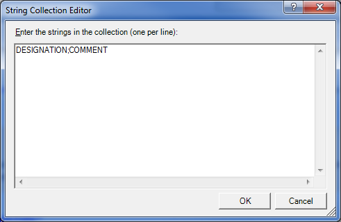
There, click on the symbol and define the desired assignments. Each assignment must be defined in one row, in the following format:
Article attribute;Document attribute
For instance, if you want to assign the article attribute NORMBEZEICHNUNG (Standard designation) of the parts to the document attribute BEMERKUNG (Comment) of the drawing, the assignment must look like this:
The article attribute NORMBEZEICHNUNG (Standard designation) of the parts will then be assigned to the document attribute BEMERKUNG (Comment) of the drawing, separated by a semicolon. Identical article attributes will be transferred only once in the process.
An example:
The model drawing consists of the 4 displayed beams with the indicated standard designations shown below.
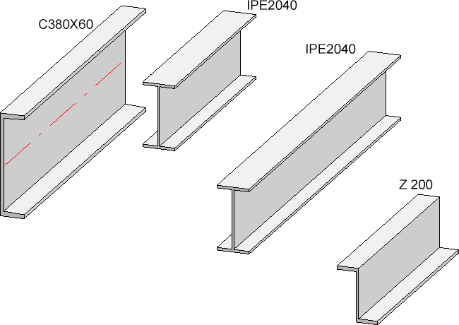
If you now create a workshop drawing containing all parts, the following string will be assigned to the document attribute BEMERKUNG (Comment) of the drawing:
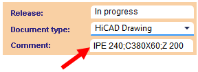
Please note that the attribute BEMERKUNG (Comment) that was used in the example is not contained in the dialogue masks by default, but needs to be added via the HELiOS Mask Editor if required!
Create sectional views when updating production drawings
Use this parameter to specify for external, PDM-managed drawings whether missing sectional views are to be created when you update the derived drawing.
The default setting is Do not adjust.
Plan types
Besides the creation of mounting, workshop and production drawings you can use the Customer drawing function to create various customer drawings for approval, e.g. builders' or architects' plans. You can specify the drawing types that are to be offered for selection via the Plan types parameter.
Pre-set has been the Customer drawing plan type (Text key STB_HELIOS_CUSTOMER_DRAWING). If you want to define other types, click the symbol in the Collection field, enter the name of the new drawing/plan type in a new line, e.g.:
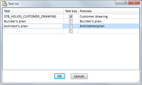
Confirm with OK.
Delete unused Sheet areas
The detail drawings created with the Management+BIM module are always stored on Sheet 2 of the drawing. When printing via the HELiOS/HiCAD Spooler, all sheets are printed - depending on the setting - i.e. also sheet areas without production drawings such as Sheet 1.
By setting the Delete unused sheet areas parameter to Yes you can now specify that sheet areas without production drawings are deleted. The default setting is No.
Rearrange views when updating production drawings and mounting drawings
Use this parameter to specify for external, PDM-managed drawings whether you want the views to be rearranged automatically in production drawings or mounting drawings upon updates. Switching this option off makes sense if, for instance, you have deliberately moved some views and want to keep their new position.
The default setting is Rearrange.
Rework of drawing
When saving drawings that were created via Management+BIM, you have the option to execute an individual script for automatic reworking. For this purpose the new parameter Rework of drawing has been added at PDM > Management+BIM > Production drawings.
There you can choose between Detail drawings, Drawings containing multiple parts, Mounting drawings, Customer drawings, and Others. "Others" are all HiCAD model drawings that do not comply with other classifications, such as 3-D models, files created with the Reference part, Save, Detail drawing function etc.
Mark the corresponding entry in the listbox to determine for which drawing types a rework via script is to be carried out, e.g.
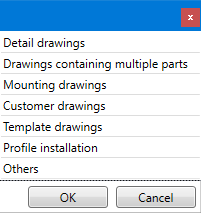
Multiple selections are also possible.
The scripts that need to be executed must have certain names. The scripts that are supplied together with HiCAD have already been predefined as follows:
|
Drawing type |
Name of script |
Active part |
|---|---|---|
|
Detail drawing |
UpdateSingleWSD.cs |
Part or Assembly |
|
Drawings containing multiple parts |
UpdateMultiWSD.cs |
Main assembly |
|
Customer drawings |
UpdateCUD.cs |
Main assembly |
|
Mounting drawings |
UpdateMTD.cs |
Main assembly |
|
Profile installation drawing |
UpdatePI.cs |
Main assembly |
|
Template drawing |
UpdateTD.cs |
Main assembly |
|
Others |
UpdateSZA.cs |
Main assembly |
The directory that is assigned to File group 2 in the FILEGRUP.DAT file has been preset as the path of the scripts. By default, this is the HiCAD directory MAKROST3D.
The file UpdateSingleWSD.CS:
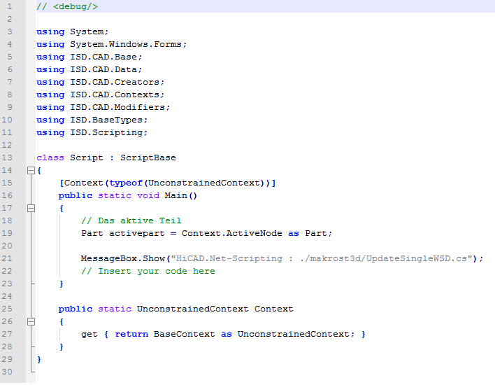
These script templates can be expanded by any API commands. For example, you could insert a bitmap with a corresponding bar code into all detail drawings in this way:

Please note however that a very good knowledge of the API is required for the creation of such individual scripts, and that the scripts (when they are activated) will be run upon every saving of the drawing, i.e. upon manual saving, creation and updating of the drawing, and its checkup and release. An appropriate message will be displayed in HiCAD after drawing creation, e.g.

Please note:
A very good knowledge of the API is required for the creation of the individual scripts.
As far as the example with the bar code is concerned: It will not be sufficient to merely add the insertion of a bar code in the script. Instead you need to ensure that the script also contains a check for an already existing bitmap and replace it. Otherwise the bitmap will be contained multiple times. HiCAD will not perform any such check.

Requirements for a Smooth Operation (ManBIM) • Management + BIM Settings in the Configuration Editor (ManBIM) • Important Information(ManBIM)