Sheet Metal - What's New?

Service Pack 2 2023 (V 2802)
Coat parts
Using the optimised Coating  function in Ribbon Sheet Metal and Steel Engineering, you define the coating description, the coating colour (RAL, NCS and system construction colour) and the coating type (outside, back/inside and face) of sheets and plates as well as beams and profiles and 3-D parts. The Extend coating
  function, with which you transfer the coating to the new or processed elements, can now also be applied to profiles.
The coating description and the coating type are transferred to the part attributes and can thus also be made available to the bill of materials.
After selecting the function, a preview of the coating is displayed for the active part (in shaded mode). You can now select other parts and apply the coating with OK.
An arrow  is visible in the middle of sheets and hollow profiles after the selection. Use this to exchange the outside with the back of sheets or the inside with hollow profiles. For non-hollow profiles, the specification for the inside has no meaning.
If you have already assigned an outer side to the sheet or plate with the function Determine visible side, this will be taken over as the outer side when coating.
You can select a RAL or NCS colour from the catalogue or a system colour or drawing colour as the coating colour. If you have selected a catalogue colour, you can also adopt the description from the catalogue. The description is transferred to the part attributes.
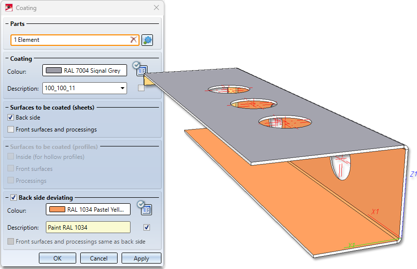
Surfaces to be coated
For sheets, you can coat the end faces and the processings either in the colour of the outer side or the back side. For profiles, you can set the coating of front surfaces and processings separately. These settings are transferred to the part attributes.
If Back side deviating is deactivated, the second colour selection is greyed out and both sides will get the same colour.
(1) Coating (outer side), (2) Back side/Inner side deviating, (3) Coat front surfaces and processings like back side of sheet, (4) Do not coat front surfaces for hollow profiles, (5) Coat processings like inner side (for hollow profiles)
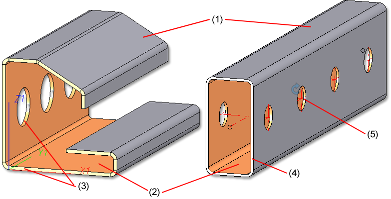
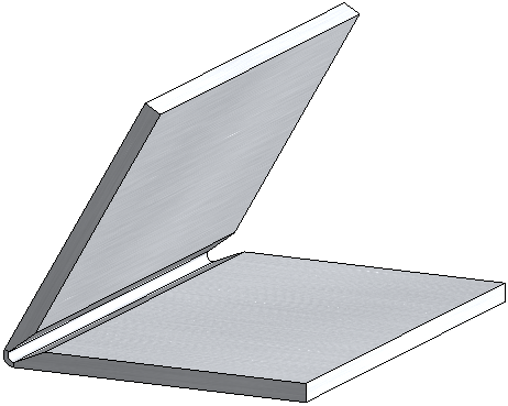
Attach flanges to surface
The Attach flanges to surface function has a new option for corner processing.
This option allows you to close the corners of sheets with milling edge zones  , taking into account the Joint, i.e. Inner edge, flush or Sheet edge as milling edge.
Joint: Inner edge, flush ![]()
With the joint you determine whether the inner flange edges are shortened or lengthened flush.
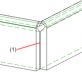
(1) Clearance
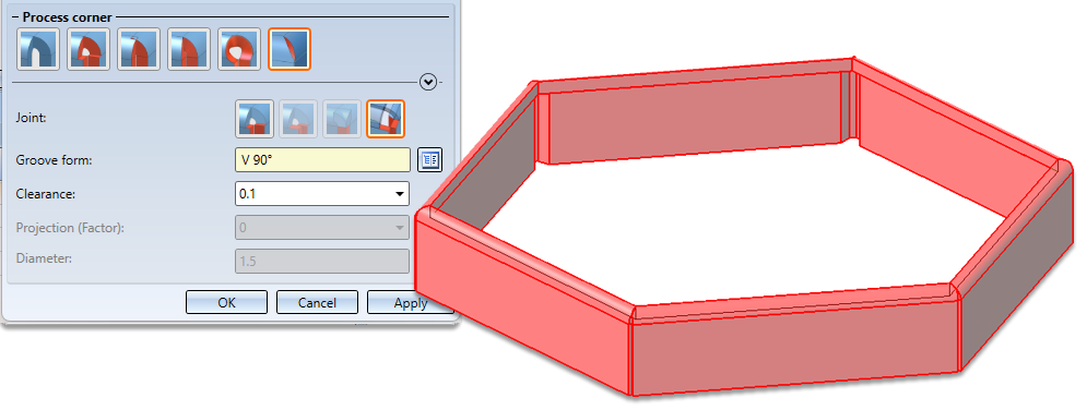
Joint: Sheet edge as milling edge 
For composite panels you can finish the flanges with a milling edge zone. For the milling edges, select the appropriate milling tool from the Groove form option in the Factory standards > Composite panels, groove form catalogue.
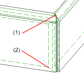
(1) Milling edge closed
(2) Groove form V 90° for the flanges from the catalogue
Copy flange or bend zone
If you copy the flange or bend zone of a Sheet Metal part using the Copy to HiCAD Clipboard  function (in the ICN toolbar or context menu), the entire Sheet Metal part is always copied if the feature is active.
You can then paste the Sheet Metal part as a new main or sub part into the current drawing or into a new drawing using the Paste from HiCAD Clipboard  function.
Clone/Transform multiple selections
If you select flanges and bend zones in multiple selections, as of HiCAD 2023 SP2 the complete Sheet Metal part is always taken for transforming and/or cloning. Previously, an error message appeared and the function was cancelled.
![]() Please note:
Please note:
For flanges and bend zones without feature, Transform and Clone operations applied to individual parts are still allowed.
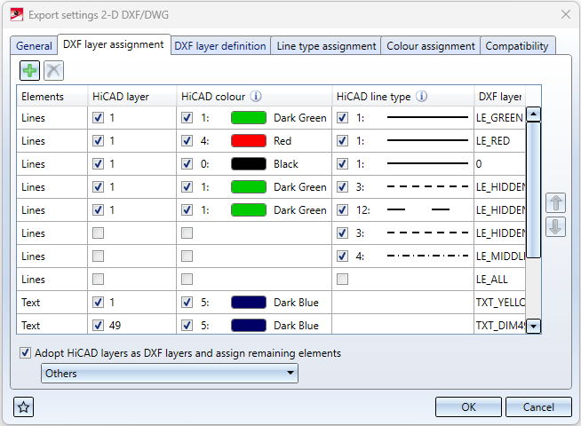
New setting options for DXF/DWG export
The dialogue for setting the DXF/DWG export options has been further modernised.
- On the General tab the option Create blocks has been added. This replaces the previous keyword FIGBL.
- Use the table on the DXF layer assignment tab to assign HiCAD elements to corresponding DXF layers. This table replaces the previous keywords LAYER, TXTLA and SONST.
- In addition, LAYER * and SONST * have been replaced by the checkbox below: Here you can choose for wHiCADh elements DXF layers should be generated (and assigned accordingly) according to the HiCAD layer of the elements.
- The properties of DXF layers can be configured on the DXF layer definition tab. This replaces the previous keyword BYLAY.
- On the Line type assignment tab, the HiCAD line types can be assigned DXF line types with name and description. This replaces the previous keyword LTDEF.
Dimensioning Rule Editor - Development view
The dimensioning rules for Development views in drawing derivations can now be defined in the Dimensioning Rule Editor. For this purpose, the dialogue window has been extended by a corresponding tab.
Please note:
In the drawing derivation, these rules are only taken into account if the options for Dimensioning are active accordingly in the Sheet development settings, e.g. Processings.
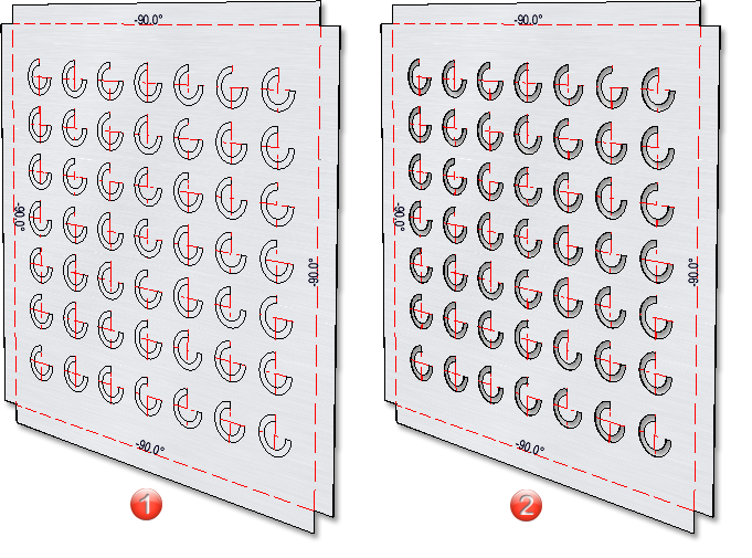
New dimensioning rules for agraffes
There are new dimensioning rules for agraffes:
- Dimension agraffes in Sheet Metal parts via dimensioning point (163)
- Dimension agraffes in Sheet Metal development via dimension point (3016)
For the two dimensioning rules, an isolated point was added to the agraffe in the bore pattern. This point serves as a dimensioning point and has the designation Dim.
Service Pack 1 2023 (V 2801)
Sheets form bend zones
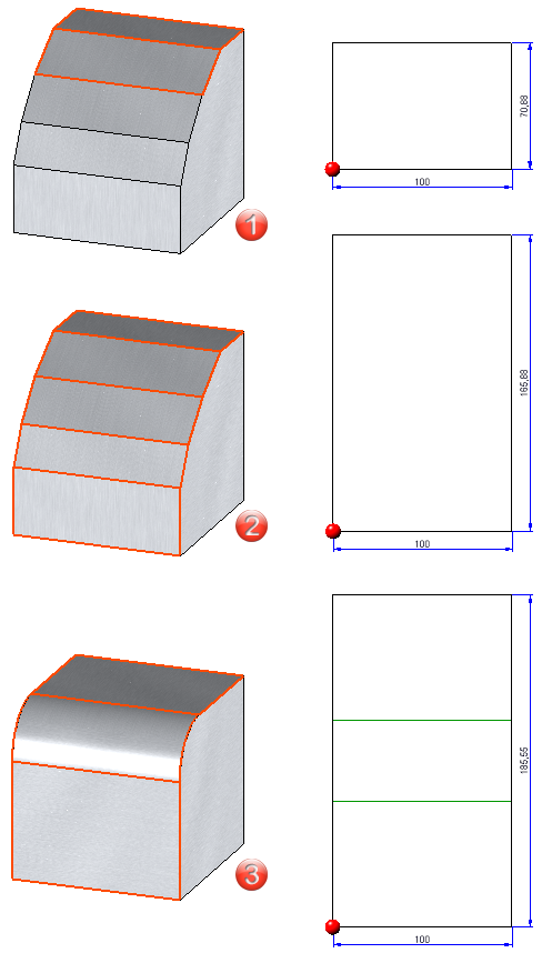
In HiCAD you can now create and edit Sheet Metal parts consisting of bend zones only. For creation, the Sheet along sketch function is available or you import a bend zone via the STEP interface. You can then perform a bending simulation, development or a sheet thickness calculation, for example.
If you have created a Sheet Metal part with the Sheet along sketch function from bend zones, then you can edit the sketch in the feature or change the bend zones via the dialogue. If the sketch contains arcs that do not merge tangentially, a bend zone will beinserted.
(1) Sketch, (2) Arcs without tangential transition, (3) Bend zones inserted
Sketch feature - Element snap mode
In HiCAD Sheet Metal, sketches are often used when creating and processing sheets. You can process these sketches via the feature log. The user guidance for the Process sketch feature has been changed.
Previously, in Element snap mode, holding down the SHIFT key while right-clicking on a sketch element highlighted the sketch and geometry in colour. This made the selection of sketch elements difficult in many cases and possibly led to errors in HCM constraints.
As of HiCAD 2023 SP1, a sketch element is selected in the drawing in Element snap mode via SHIFT + right click and then the Process sketch function is called in the context menu for edges. Afterwards, only the sketch is marked in colour and the feature is calculated up to the initial position.
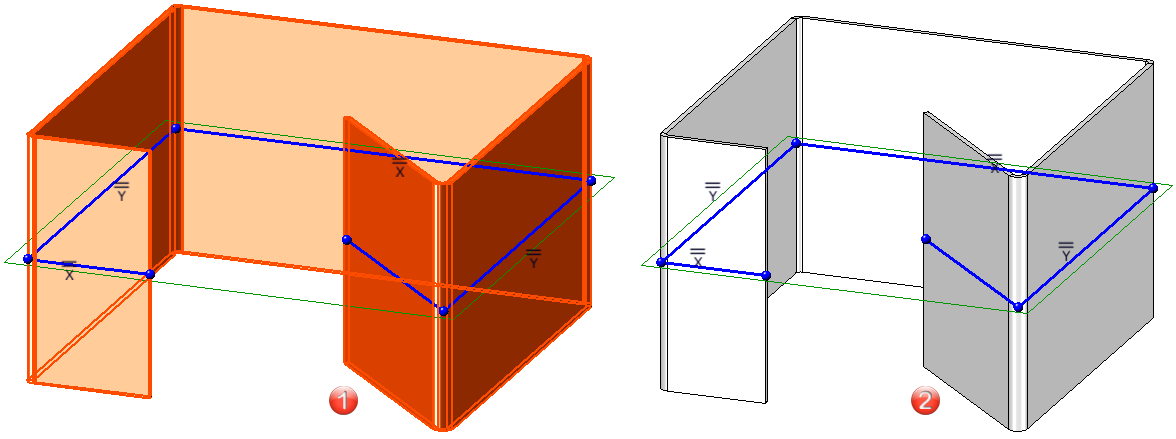
(1) Behaviour before HiCAD 2023 SP1
(2) Behaviour as of HiCAD 2023 SP1
Configuration of the graphic display
The display, e.g. when working with sketches, when lengthening sheets or filleting, can be configured. At System settings > Identification you can set the Text colour, Text background colour, Display height and Line colour for the preview dimension display.
Check part orientation of Sheet Metal parts
For Drawing derivation you can check whether a particular Sheet Metal part has a part orientation. To do this, open the Configuration Editor, go to Automatic drawing derivation > Production drawing and activate the checkbox Check part alignment for Sheet Metal parts.
If you then have not defined a part orientation, a message will be displayed during drawing derivation.
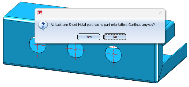
If you choose Yes, the drawings will be created. If you choose No, you cancel the drawing derivation.
With the Part orientation function you determine the front view or top view of the sheet. You define the part orientation with the functions Orient...  (Drawing > Positioning/Detailing) or via the context menu of the Sheet Metal part (Properties).
![]() Please note:
Please note:
When you create a sheet using the Sheet along sketch function, both the part orientation and the dimension orientation are automatically set to the front view of the sheet.
Major Release 2023 (V 2800)
Change length
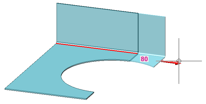
On the Sheet Metal tab, the lengthening of sheets in the same plane is summarised in the Change length  dialogue. With the dialogue you can lengthen flanges and bend zones as you like or shorten them by a negative value or by selecting the direction. You can also change the length in the bending simulation.
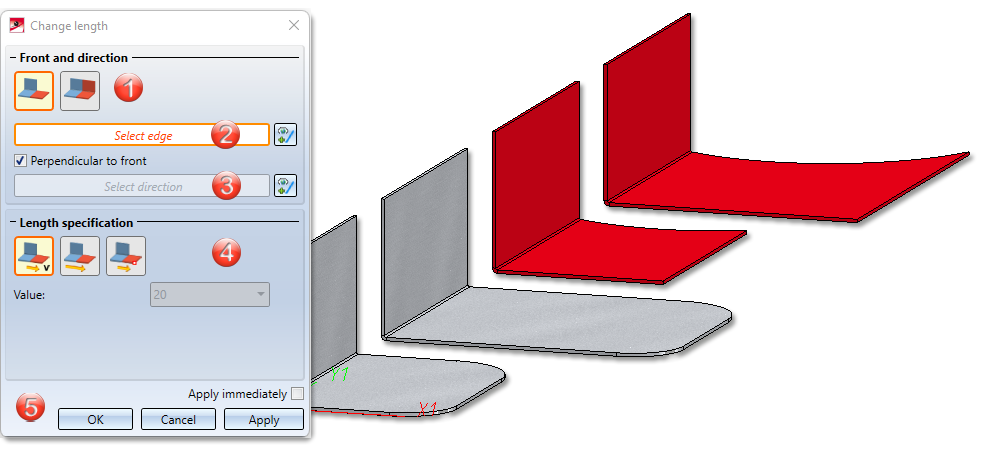
Select via the icon whether you want to lengthen a flange or a bend zone, a milling edge zone or the entire sheet with bend zones and flanges.
|
|
Only selected surface |
If you have activated this icon, you can change the length of a flange or a bend zone or a milling edge zone. |
|
|
All surfaces in same plane |
Bend zones and flanges that are in the same plane are lengthened in one step. |


By identifying the edge, a top surface, a front surface and the front edge in between are now clearly determined. If you activate the option Perpendicular to front, the direction is automatically determined and displayed on the flange.
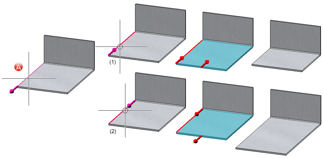
(A and B) The identification point of the edge determines the front side.
(1), (2) and (3), (4) When selecting the direction, an arrow is displayed for clarification.
You have three options for length specification:
- By value: This option lengthens a flange/bend zone or a complete sheet by the entered value, depending on the previous selection.
- Total length: Lengthens a flange/bend zone or sheet by entering the new total length. The total length refers either to the flange/bend zone or to the complete sheet.
- To point: Lengthens a flange/bend zone or a sheet in the selected direction over a point and a distance to the point.
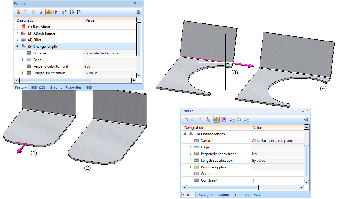
(1) and (2) Lengthening of the surface by selecting the front edge (right-click))
(3) and (4) Lengthening of the sheet perpendicular to the front by selecting the longitudinal edge.
Develop surfaces (analytical)
The completely revised Develop surfaces function analytically develops the surface of a 3-D part (e.g. truncated cone or free-form surface). Either a sheet thickness (offset) is queried for the depth of cut or, for example, the thickness is adopted for hollow bodies.
You can derive several 3D developments with different parameter settings from one 3-D part. The parameter settings are saved with the development. A new view is created for each development. The view and the 3-D part are linked. If the sheet metal part is deleted, the view with the development also disappears.
In the ICN, the development appears below the 3D part and can contain sketches as a secondary part for later processing with 3-D functions. If the development is active, the 3-D part is greyed out.
You have the option of defining the development parameters when creating the development. You can access the functions for changing the parameters by right-clicking on the development.
After activating the function, the following dialogue appears.
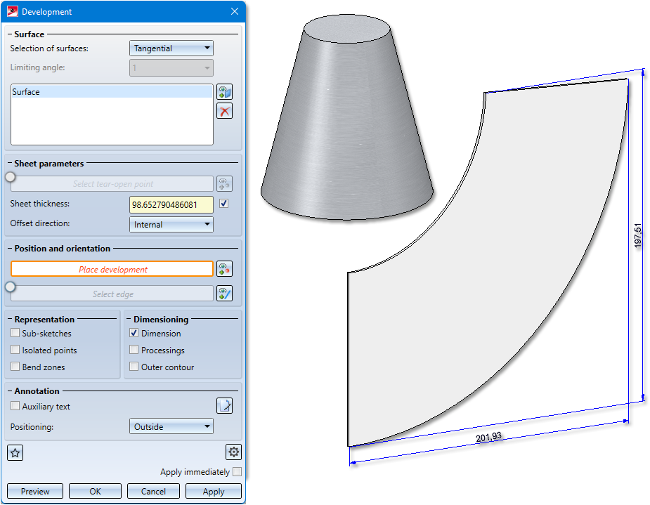
The 3 options Individual, Tangential and Tangential with angle are available for the selection of the surfaces to be developed.
(1) Individual: Here you select the surfaces to be developed individually.
(2) Tangential with angle: Adjacent surfaces and tangential surfaces are automatically recognised taking into account an angle.
(3) Tangential: Tangentially adjacent surfaces are recognized automatically.
With the help of the Annotation Editor, you can define additional texts, e.g. for production, or load the annotation via the Favourites. The attributes that can be evaluated are displayed in the Annotation Editor. These can be supplemented with your own notes.
In the Extended settings, the line colour, line type and the layer of the various edges are set. For example, you can set the colour, line type and layer in the development for crosshairs.
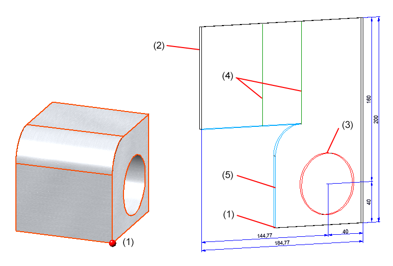
(1) Tear-open point, (2) Sheet development edges, (3) Inner contours, (4) Bend zome, (5) Tear-open edges
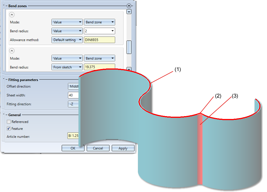
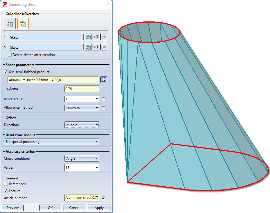
Connecting sheet
With the modernised Connecting sheet function you can connect two composite edges (guidelines), from a 3-D sketch or a planar sketch, with a sheet. Depending on the selected function, the sheet is created as a main or sub-part. As soon as your entries are sufficient, a preview is displayed. The feature log is available for changes.
Connecting sheets can be derived from planar sketches and 3-D sketches. In the 3-D sketches, both composite edges can be in one 3-D sketch if the  icon is active. If the composite edges are in two 3-D sketches or if you are working with plane sketches, activate the following icon
  . Make sure that there is only one composite edge in the sketch.
If you choose a semi-finished product  from the Catalogue Editor
  , the sheet thickness is not requested. The sheet thickness and, if applicable, the Article number are then taken over from the Catalogue Editor for the sheet. In the General area you can also change the Article number for the selected semi-finished product. If you also want to take over the bend radius from the Catalogue Editor, activate the checkbox next to the Bend radius input field. Proceed in the same way with the Allowance method.
Under Offset you select to which side the sheet thickness (material thickness) is to be removed.
The following options are available for the processing of bend zones:
|
|
No special processing |
Bend zones that meet in a corner of the sheet are shortened to avoid overlapping. |
|
|
Flush |
If several bend zones converge in one corner, the sheet is widened in the corner to make room for the bend zones. The front surfaces of the bend zones are flat surfaces. They are not adjusted to the adjacent flanges.. |
|
|
Flush and corrected |
If several bend zones converge in a corner, the sheet is widened in the corner. The front surfaces of the bend zones are adjusted to the adjacent flanges. |


The arcs of the guidelines are approximated synchronously by polygon lines so that two lines lie in one plane and thus define a flange. You define the accuracy of the resulting sheet metal flanges in the Accuracy criterion area.
Inputs that cannot be evaluated are marked with the  symbol.
Once you have entered all the required data, the connecting sheet can be inserted as shown in the preview. If you select Apply or press the middle mouse button, the flange is inserted, but the dialogue window remains open - in contrast to OK. This way you can change the data and assign it to other sketches with Apply.
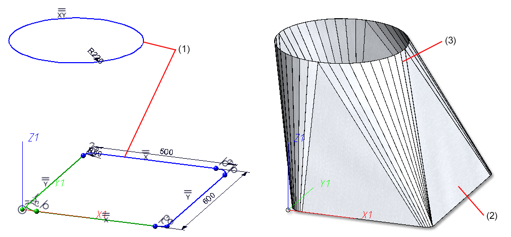
(1) First and second guideline in a 3-D sketch
(2) Connecting sheet
(3) Accuracy criterion: Angle 5
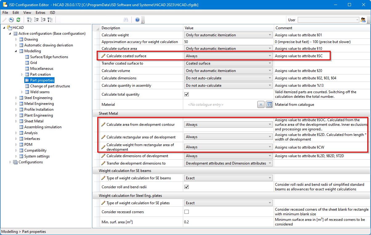
New attributes for calculating the surface area of sheet metal parts
In HiCAD, new system attributes are available for sheet metal parts and coated surfaces:
|
§SOC |
Calculate surface area from the development contour, internal exclusions and processings are ignored |
|
§S2D |
Calculate rectangular surface area of the development from length * width |
|
§CW |
Calculate weight from the rectangular surface area of the development |
|
§SC |
Calculate the coated surface area for coated sheet metal parts |
In the Configuration Editor, at Modelling > Part properties, you set the system attributes for when the calculation should take place, e.g. for the creation of bills of materials.
The following three procedures are available for selection:
- Do not auto-calculate
- Only for automatic itemization
- Always
2-D DXF/DWG export with new settings
In order to be able to edit the settings more comfortably when exporting developments as 2-D DXF/DWG files, new functions have been integrated.
These replace the manual editing of system files (acadhcad.dat, hcadacad.dat), which are thus no longer required in this form.
However, settings from older configuration files can still be read in and taken into account accordingly.
You can load the ISD defaults with this icon  , customise them with the Edit settings
 function and then save them as Favourites under a new name. .
Planar symbol for all processings in the development
For developments, symbols can be output for processings (bore patterns, punching tools, ...). To do this, the symbol must be entered in the TOPSYMBOL and BOTTOMSYMBOL columns in the Catalogue Editor.
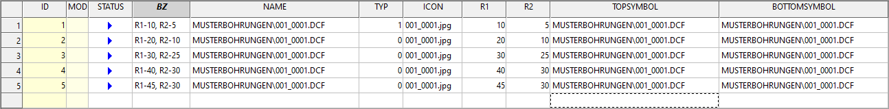
You can also extend tables (e.g. countersinks) with these columns yourself and thus output symbols during development. To do this, add the TOPSYMBOL and BOTTOMSYMBOL columns to the table in theCatalogue Editor and then enter a relative path to the symbol file. This can be 2-D/3-D parts (FGA, KRA) or HCM models (DCF).
In the development, select the option Planar symbol from catalogue on the Extended representation tab in the Extended settings dialogue.
![]() Please note:
Please note:
To read out the symbol in the development, processing must be done in the sheet metal flange..
(1) The planar symbol from the catalog is displayed.
(2) Example of a bore pattern displayed in the development
Part orientation in workshop drawings for New sheet along sketch function
Up to now, with the New sheet along sketch function, the part orientation of the front view was placed on the cross-section surface. However, this is not useful for the workshop drawing, as the front view is evaluated for the drawings. Therefore, the front view is now placed on the sheet so that the drawings can be evaluated better.
When creating a sheet along a sketch, both the part orientation and the dimension direction are set.
New groove form for milling edge zones
In the catalogue Factory standards > Composite panels, groove form, the table Standard groove form has been extended by an entry for easy fiX side milling cutters V 135°, 3 mm. This groove form can be selected when attaching flanges.
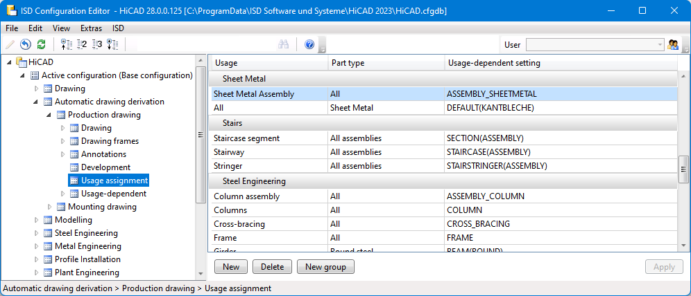
Drawing derivation: New Usage for Sheet Metal assemblies
For Sheet Metal assemblies, i.e. assemblies with a Sheet Metal part as the main part, a new usage is available: Sheet Metal Assembly. The catalogue Factory standards > Usage has been extended accordingly.
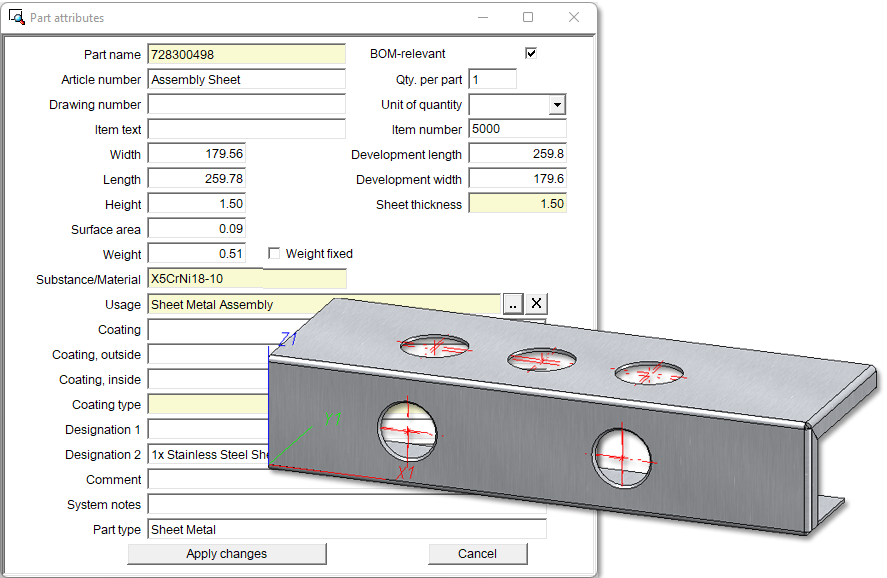
For assemblies with this usage, usage-dependent configurations can be used for the drawing derivation, which are managed in the Configuration Editor as with other usages. For assemblies with the usage Sheet Metal Assembly the configuration ASSEMBLY_SHEETMETAL is predefined.

HiCAD Sheet Metal • General Notes on Sheet Metal Processing • Overview of Functions (3-D SM)