Sheet Metal > Change length 
On the Sheet Metal tab, the lengthening of sheets in the same plane is summarised in the Change length dialogue. With the dialogue you can lengthen flanges and bend zones as you like or shorten them by a negative value or by selecting the direction. You can also change the length in the bending simulation.
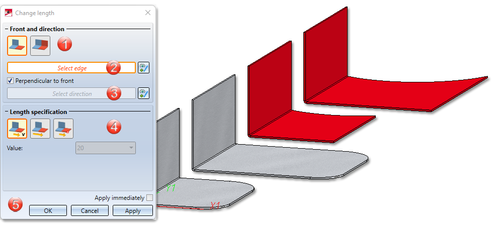
- First select via the icon whether you want to lengthen a flange or a bend zone, a milling edge zone or the entire sheet with bend zones and flanges.
|
|
Only selected surface |
If you have activated this icon, you can change the length of a flange or a bend zone or a milling edge zone. |
|
|
All surfaces in same plane |
Bend zones and flanges that are in the same plane are lengthened in one step. |


- Identify an edge of the longitudinal side or the front side with a right-click.
- Then determine the direction of the lengthening.
If you activate the option Perpendicular to front, the direction is automatically determined and displayed on the flange.
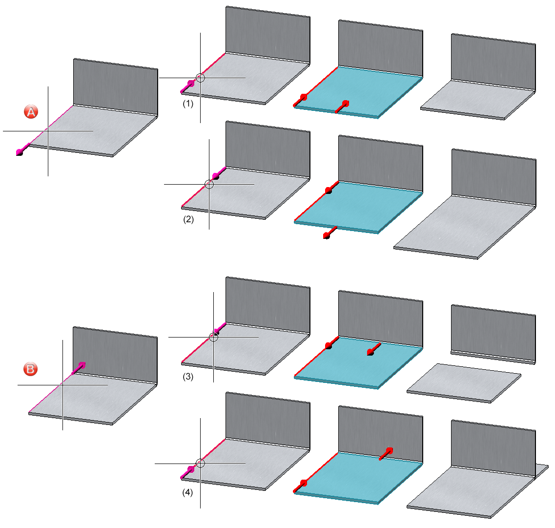
(A and B) The identification point of the edge determines the front side.
(1), (2) and (3), (4) When selecting the direction, an arrow is displayed for clarification.
If you want to identify another edge or direction, select the  icon for identification.
- Then enter the length specification.
|
Length specification |
||
|---|---|---|
|
|
By value |
This option lengthens a flange/bend zone or a complete sheet by the entered value, depending on the previous selection. |
|
|
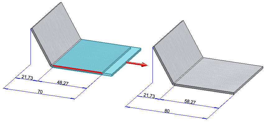
Total length |
Lengthens a flange/bend zone or sheet by entering the new total length. The total length refers either to the flange/bend zone or to the complete sheet.
Total length of flange changed |
|
|
To point |
Lengthens a flange/bend zone or a sheet in the selected direction over a point and a distance to the point. |


- Apply the preview with OK.
If you select Apply or press the middle mouse button, the function is executed, but the dialogue window remains open - unlike OK. This way you can change the data and extend another sheet with Apply. If you leave the dialogue window with Cancel, the function is cancelled without installation or modification. If you have ticked the Apply immediately option, the data will be applied directly if it is complete.
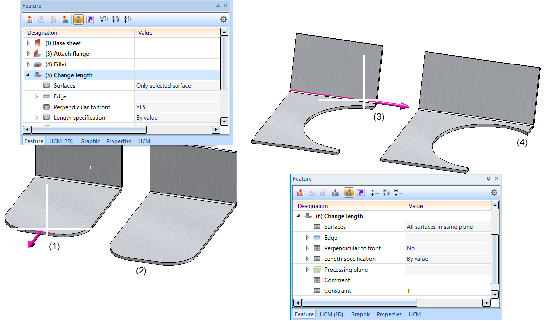
Subsequent changes are made via the feature log. The lengthening of plates is highlighted in the model drawing when the feature is activated. The displacement vector is represented by an arrow from the start point to the end point of the vector.
![]() Please note:
Please note:
Incorrect entries are indicated by this  symbol. Move the cursor over the symbol to display the error message.
If the function cannot be executed with the entered data, this symbol  will appear on the OK button. Move the cursor over the symbol to display the error message.
(1) and (2) Lengthening of the surface by selecting the front edge (right-click))
(3) and (4) Lengthening of the sheet perpendicular to the front by selecting the longitudinal edge.


Overview of Functions (3-D SM) • General Notes on Sheet Metal Processing (3-D SM)