Sheet Metal > Attach > Flange  > Flanges to surface
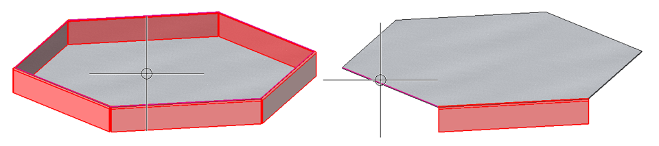
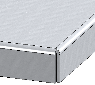
To attach flanges around a surface, several variants for corner processing can be chosen in the dialogue window after activating the function. You can assign different parameters to the flanges.

Areas of the dialogue window:

Outer connecting edges
The choice of the first connecting edge determines the cover surface and thus also the direction of the flanges. If you select a surface instead of individual connecting edges, all outer edges are used for the attachment. To delete individual edges, click on the desired attachment in the drawing. It will then be removed from the list.
After selecting the outer connecting edge, you will be shown a preview of the new flanges, provided you have not activated any options that require further specifications.
After selecting the cover surface or the connecting edge, a preview of the possible flanges is displayed.
If you want to identify more edges, click on the  icon in the Outer connecting edge area. You can delete connecting edges by right-clicking them in the Attachments area.
![]() Please note:
Please note:
During data entry, you can cancel the function with the middle mouse button if no preview is displayed yet. Otherwise, accept the preview by pressing the middle mouse button.
Parameters
The Parameters area offers the following options:
Reference and Length
You can enter the length of the flange via a numerical value. If you click with the right mouse button in the Length input field, you can e.g. take the length from the drawing with the option Pick distance.
There are several ways to define the reference of the length
|
|
Angle-dependent, outer For angles up to 90° like "Direct, outer"; otherwise like "Direct, to outer tangent" |
|
|
|
Angle-dependent, inner For angles up to 90° like "Direct, inner"; otherwise like "Direct, to inner tangent" |
|
|
|
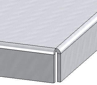
Direct, outer Flange length up to intersection point of the outer flange surfaces |
(1) New flange |
|
|
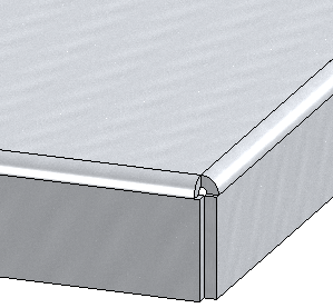
Direct, inner Flange length up to intersection point of the inner flange surfaces |
(1) New flange |
|
|
Direct, to outer tangent Flange length up to the surface of the bend zone |
(1) New flange |
|
|
Direct, to inner tangent Flange length up to the inner surface of the bend zone |
(1) New flange |
|
|
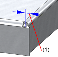
Outer distance Vertical distance of the end of the new flange measured at the outer surfaces of the flanges |
(1) New flange |
|
|
Inner distance Vertical distance of the end of the new flange measured at the inner surfaces of the flanges |
(1) New flange |


Angle
The bend angle can be entered directly or taken from the drawing by right-clicking in the input field with the Pick angle option.
Fitting mode
The fitting mode refers to the processing of the connecting flange. The following options are available:
|
|
Shorten, outer The connecting flange is shortened in this mode. The outer flange surfaces intersect in the plane of the front surface before the shortening. |
(1) Connecting flange |
|
|
Shorten, inner The connecting flange is shortened. The inner flange surfaces intersect in the plane of the front surface before the shortening. |
(1) Connecting flange |
|
|
Without shortening In this fitting mode, the connecting flange remains unchanged. |
(1) Connecting flange |
|
|
Shorten, outer tangent The connecting flange is shortened. The outer surface of the bend zone touches the plane of the front surface before the shortening. |
(1) Connecting flange |

|
Shorten, inner tangent The connecting flange is shortened. The inner surface of the bend zone touches the plane of the front surface before the shortening. |

(1) Connecting flange |
|
|
Angle, dependent, outer For angles up to 90° like "Shorten, outer"; otherwise like "Shorten, outer tangent" |
|
|
|
Angle-dependent, inner For angles up to 90° like "Shorten, inner"; otherwise like "Shorten, inner tangent" |
|


Mode of the bend zone
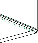
Composite sheets, such as ALUCOBOND® panels, are formed using milling edge technology. The resulting bend zones differ geometrically from the cylindrical bend zones. Therefore, in HiCAD you have the option of selecting milling edge zones instead of bend zones.
The following modes are available:
|
|
Bend zone The bend zone has the specified bend radius. |
|
|
|
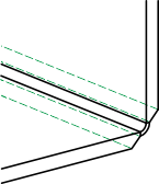
Milling edge zone Bend zone with the selected tool (milled inside). |
|
|
|
Milling edge zone, inverted Bend zone with the selected tool (milled outside). |
|


Bend zone
If you have chosen Bend zone, you can optionally select the Bend radius and the Allowance method.
The bend radius is on the inside of the bend zone. If you right-click the input field, you can pick the radius from the drawing. If the checkbox next to Bend radius is active ![]() and you have also activated the semi-finished product, the radius is loaded from the catalogue.
and you have also activated the semi-finished product, the radius is loaded from the catalogue.
To obtain the blank (development) of the modelled sheet metal part, HiCAD offers you the development according to different calculation methods (so-called allowance methods), which take into account the material-dependent length change of the workpiece that occurs during bending. HiCAD offers empirical allowance methods, which are also common in practice.
One specific calculation method is represented by one specific system file. These files are prepared as examples, but in practice every user will store one or more methods in this way himself. You can select a system file here before you click on it.
Milling edge zone
You can select the appropriate milling tool for the milling edges with the option Tool from the catalogue Factory standards > Composite panels, groove form.
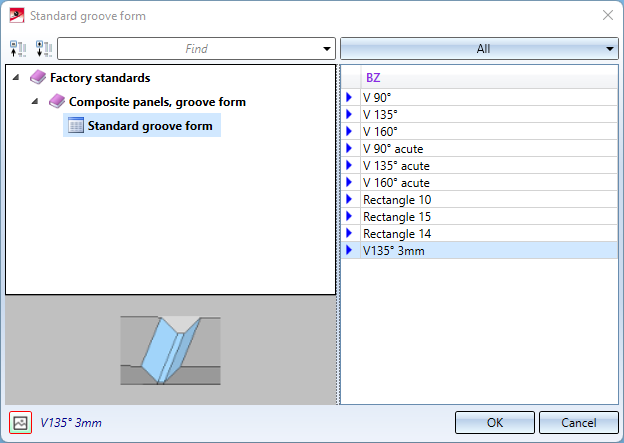
If you set the checkmark for Tool  , a tool will be loaded automatically, depending on the selected bend angle and the assignment in the catalogue (column SORT).
The ISD default setting is as follows:
|
Bend angle |
Groove form |
SORT (assignment to bend angle) |
|
≤ 90° |
V 90 ° |
1 |
|
91° - 135° |
V 135° |
2 |
|
136° - 160° |
V 160° |
3 |
|
161° - 180° |
Rectangle 10 |
10 |
The milling cutters for acute bendings are intended for 2-D designs. There, tray panels are imagined simplified as paper models. In HiCAD, the cutters with priority (SORT column) 1-3 and 10 are used by default. If you design in the paper model and want to use the groove forms for acute bendings automatically, you have to change the priority. For example, the groove form V 90° is assigned a 6 in the column SORT and V 90° acute is assigned a 1.
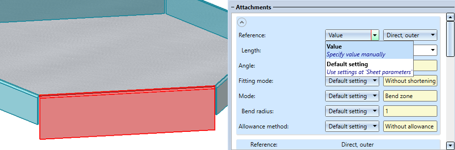
Attachments
In the Attachments area, you can change the default setting from the Parameters section for each flange individually.
For example, if you want to change the length, mode, bend angle or allowance method for an attachment, click on the  icon to expand the area and select a Value instead of the Default setting. Then enter the new value.
With a right-click you can delete the attachment  from the list.
Process corner
The type of corner processing can be combined with the selected type of joint:
|
|
Off (No processing) No corner processing takes place. The following parameters for the joint and clearance are therefore deactivated. |
|
|
|
Close corner, free If this option is chosen, the bend zone is not processed. You can enter clearance for the flange. The processing of the flange is determined by the joint. |
(1) Projection |
|
|
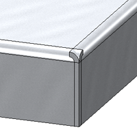
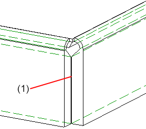
Close corner, closed Here the bend zone is closed, i.e. the sheets and the bend zones are lengthened up to the common intersection of the inner and outer edges, taking the clearance into account. |
(1) Projection
|
|
|
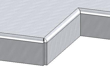
Close corner, drainage area If this option is chosen, flanges around a surface (base sheet) with a drainage area are attached, taking the clearance into account. |
|
|
|
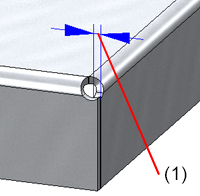
Close corner, round Here the bend zone is provided with a relief groove. You can either enter the diameter freely or load it from the catalogue if you have entered a semi-finished product for the base sheet. Activate the semi-finished product using the checkbox |
(1) Projection |
|
|
Close corner, milling edge Here the corners of sheets with milling edge are closed taking into account the Joint, i.e. Inner edge, flush or Sheet edge as milling edge. |
(1) Clearance
(1) Milling edge closed |


 Joint:
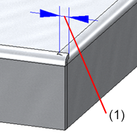

 next to the
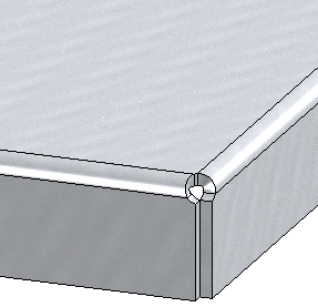

 Joint:
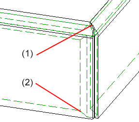
Apply/discard value inputs
Once you have entered all the necessary data, the new flanges can be inserted. If you select Apply or press the middle mouse button, the flanges are installed, but the dialogue window remains open - in contrast to OK. This way you can change the data and assign them to other connecting edges with Apply. If you leave the dialogue window with Cancel, the function is cancelled without an insertion or modification taking place.
![]() Please note:
Please note:
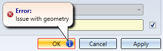
If the function cannot be executed with the entered data, the  symbol appears at the OK button. Move the cursor over the symbol to display the error message
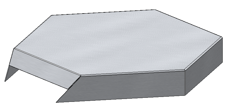
Flanges on surface with drainage area and clearance, flanges with different angles and lengths
