With the Part orientation  function you determine which view of the Sheet Metal part is to be considered as front view or top view during the Drawing derivation.
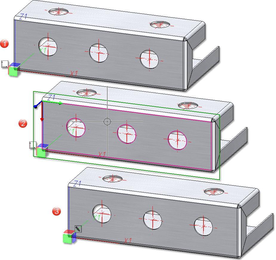
(1) Part orientation not set
(2) Determine front view as when selecting processing planes
(3) The identifier has been changed accordingly
If you have activated the option Check part orientation for Sheet Metal parts (Automatic drawing derivation > Production drawing) in the Configuration Editor, a message appears when deriving without part orientation:
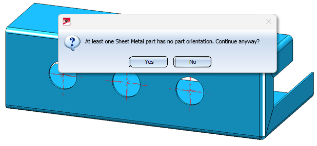
If you select Yes, the drawings are created. If you select No, the drawing derivation will be cancelled. You can also check the part orientation in the Design Checker, independently of the setting in the Configuration Editor.
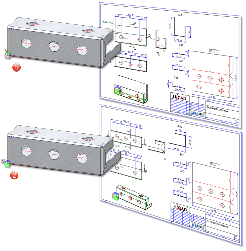
(1) Sheet with 2 bores defined as front view
(2) Sheet with 3 bores defined as front view
Part orientation for sheet along sketch
With the Sheet along sketch function, the part orientation and also the dimension orientation are automatically set to the front view of the sheet. Of course, you can change this orientation at any time.
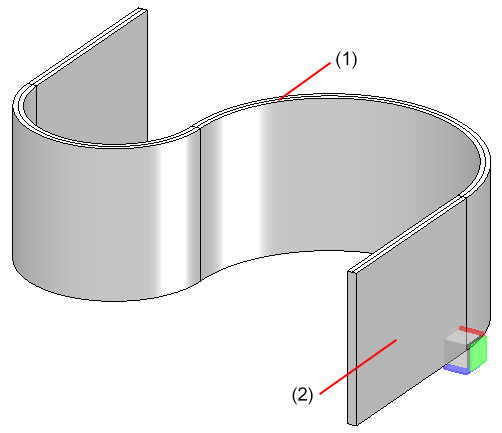
(1) Sketch, (2) Front view


HiCAD Sheet Metal • Overview of Functions (3-D SM) • News (3-D SM) • General Notes on Sheet Metal Processing