Sheet Metal > Sheet development >Dev. > Develop surfaces
This function analytically develops the surface of a 3-D part (e.g. truncated cone or free-form surface). Either a sheet thickness (offset) is queried for the depth of cut or, for example, the thickness is adopted for hollow bodies. For filleted surfaces, this results in changes in the area of the development.
You can derive several 3D developments with different parameter settings from one 3-D part. The parameter settings are saved with the development. A new view is created for each development. The view and the 3-D part are linked. If the sheet metal part is deleted, the view with the development also disappears.
In the ICN, the development appears below the 3D part and can contain sketches as a secondary part for later processing with 3-D functions. If the development is active, the 3-D part is greyed out.
You have the option of defining the development parameters when creating the development. You can access the functions for changing the parameters by right-clicking on the development.
After activating the function, the following dialogue appears.

- Selection of surfaces
- Sheet parameters
- Position and orientation
- Representation, Dimensioning
- Annotation
- Favourites
- Extended setttings
- Apply /discard inputs
- Info in case of incorrect inputs
- Example
![]() Please note:
Please note:
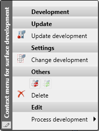
Right-clicking a development opens a context menu with further processing functions.
If you move the mouse over a text on the 3-D development, the text is displayed in magenta. Now click on the text with the left mouse button and hold the mouse button printed then you can move the text. When you update the development, the text is moved back to its original position.

Selection of surfaces
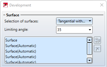
The 3 options Individual, Tangential and Tangential with angle are available for the selection of the surfaces to be developed.
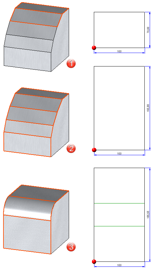
(1) Individual: Here you select the surfaces to be developed individually.
(2) Tangential with angle: Adjacent surfaces and tangential surfaces are automatically recognised taking into account an angle.
(3) Tangential: Tangentially adjacent surfaces are recognized automatically.
If you want to select different surfaces, click on the  symbol and identify the desired surface.
Sheet parameters
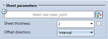
The tear-open point determines the dividing line of the surface. You can change the parameters (colour, type and layer) of the Tear-open edges in the Extended settings  dialogue window.
You can accept the Sheet thickness automatically  , e.g. for a hollow body, or enter it freely. The Offset direction determines the side to which the sheet thickness is to be applied.
Position and orientation
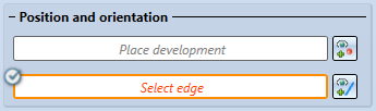
If you click on the icon for placing the development  after selecting the area, the development is displayed at the cursor and can be inserted into the drawing. You can change the position of the development by adding an edge
  .
.
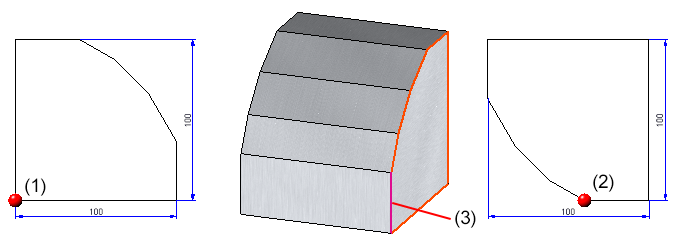
(1) Position of the development without selection of an edge
Position of the development with selection of an edge (3)
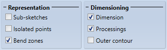
Representation, Dimensioning
Sketches that lie on a surface to be developed can be displayed by activating this option.
Isolated 3-D points of the part can be shown or hidden. The position of the points (in the development) refers to the surface that was active during the creation. The setting only affects the Isolated 3-D points that the part brings along. Points isolated later in the development are always visible.
The Bend zones can be activated or deactivated under Representation. colour, line type and layer can be specified in the Extended settings .
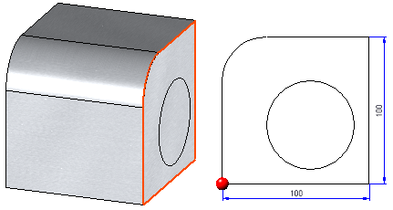
With the option Dimensions only the largest extension in X- and Y-direction is dimensioned.
With Outer contour the complete contour is dimensioned.
If you have activated Processings dimension chains are also created for holes and subtractions.
Annotation
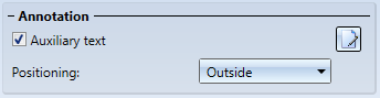
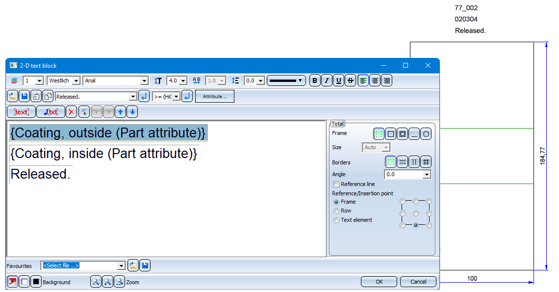
Here you configure the additional text of the development, e.g. for production. You can define the texts with the help of the Annotation Editor or load the annotations via the Favourites  . To start the Annotation Editor, click on the
  symbol next to the option. In the Annotation Editor, the attributes that can be evaluated are displayed. These can be supplemented with your own annotations.
Favourites
The settings of the dialogue window can be saved as favourites and reused at any time. To do this, click on the  symbol at the bottom left of the dialogue window.
For more information on managing favourites, see the topic Manage Favourites in the HiCAD Basics Help chapter..
Extended settings
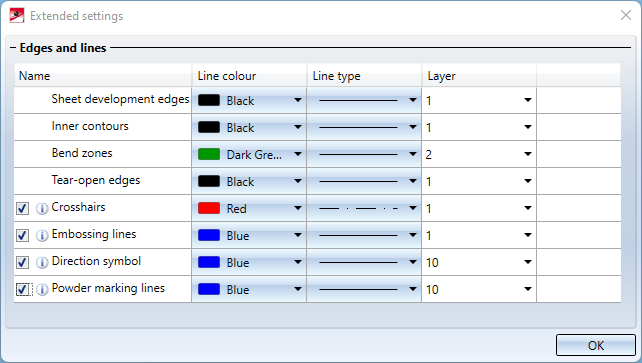
In the Extended settings, you can set the line colour, line type and layer of the different edges. For example, you can set the colour, line type and layer in the development for crosshairs here.
Please note the following for the settings for crosshairs, embossing lines, direction symbols and powder lines:
- If the checkbox is activated , the settings selected in the dialogue shown above are used.
- If you deactivate the checkbox
 , the line parameters of the original part will be used for processing.
Example:
The original part contains holes whose crosshairs are displayed red. Now select blue as the colour for the crosshairs in the dialogue. In order for them to be displayed blue in the development, you have to check this box. Otherwise, the crosshairs are displayed in red as in the original sheet..
Different parameters can be assigned to inner and outer contours (sheet development edges). Inner contours are all contours that have to be cut out of the 3-D part and are not standard processings. This makes it possible, for example, to define more clearly the adjustment of the layers in the DXF output.
Apply/discard inputs
Once you have entered all the necessary data, the development can be accepted. If you select Apply or press the middle mouse button, the development will be inserted, but the dialogue window remains open - in contrast to OK. This way you can change the data and create another development with Apply. If you leave the dialogue window with Cancel, the function is cancelled without installation or modification. With Preview you update the development after changes in the dialogue. The development must be placed in the drawing.
If you have activated the Apply immediately checkbox , the parameters will be applied immediately if they make sense and you can create a new development.
Info in case of incorrect inputs
Incorrect inputs are marked with this symbol  . Move the cursor over the symbol to display an error description.
If the function cannot be executed with the entered data, this symbol  appears on the OK button. Move the cursor over the symbol to display an error description.
If the development cannot be calculated completely, an error message appears.
Example
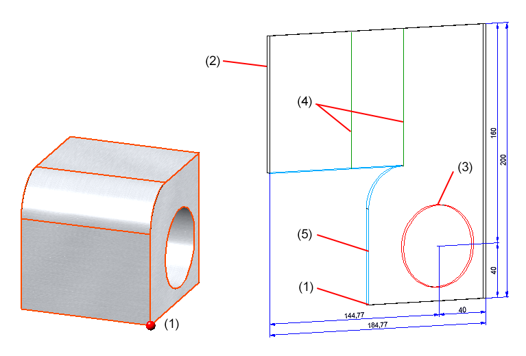
(1) Tear-open point, (2) Sheet development edges, (3) Inner contours, (4) Bend zome, (5) Tear-open edges
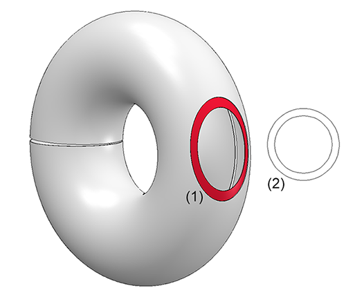
(1) Selection of the surface (Individual), (2) 3-D development

Overview of Functions (3-D SM) • General Notes on Sheet Metal Processing (3-D SM) • Sheet Development (3-D SM) • Development Parameters (3-D SM) • Update Development (3-D SM) • Process Development (3-D SM)