Sheet Metal > New > Connect 
Sheet Metal > New > Connect  > Sub-part
With these functions you can connect two composite edges (guidelines) with a sheet. Depending on the selected function, the sheet is created as a main or sub-part. To create a sub-part, you must first create a main assembly or an assembly. If the assembly is then active, the sheet metal is subordinated to the assembly after the function has been selected.
As soon as your entries are sufficient, a preview is displayed. The feature log is available to you for changes.
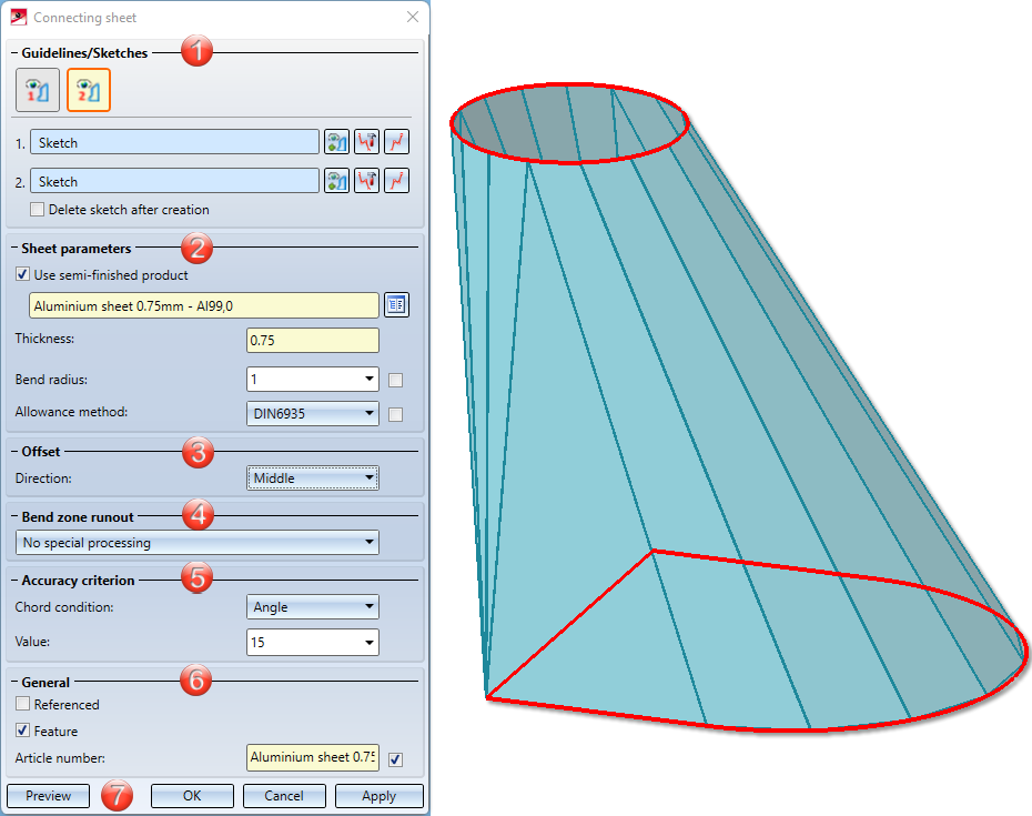
- Guidelines/Sketches
- Sheet parameters
- Offset
- Bend zone runout
- Accuracy criterion
- General
- Apply/discard inputs
- Example

Guidelines/Sketches
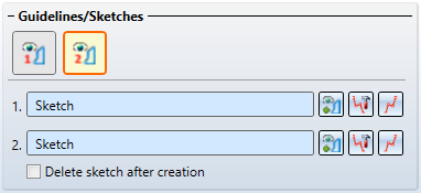
Connecting sheets can be derived from planar sketches and 3-D sketches. In the 3-D sketches, both composite edges can be in one 3-D sketch if the  icon is active. If the composite edges are in two 3-D sketches or if you are working with plane sketches, activate the following icon
  . Make sure that there is only one composite edge in the sketch.
- Select the number of sketches .
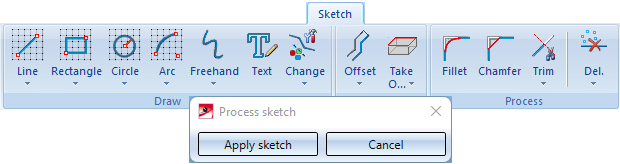
- Then use the 3-D Sketch technology
 to draw the composite edges (guidelines) to be connected.
 - Then end the sketching mode with Apply sketch.
You can also select  and process
  existing composite edges.
If the icon for selecting two sketches is active, you can also create two planar sketches  or select them from the drawing. To change the sketch, click the Process sketch icon. The menu bar with the sketch functions and the editing dialogue are displayed. Use the edit dialogue box to finish editing the sketch.
Click Delete sketch if you want to delete the sketch from the drawing and from the ICN after creating the base sheet.
Sheet parameters
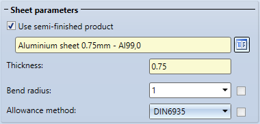
- Specify the thickness of the sheet or choose a semi-finished product.
If you choose a semi-finished product  from the Catalogue Editor
  , the sheet thickness is not requested. The sheet thickness and, if applicable, the Article number are then taken over from the Catalogue Editor for the sheet. In the General area you can also change the Article number for the selected semi-finished product. If you also want to take over the bend radius from the Catalogue Editor, activate the checkbox next to the Bend radius input field. Proceed in the same way with the Allowance method.
By double-clickin on the feature Connecting sheet you can activate, deactivate or change the semi-finished product at a later time if desired.
Offset
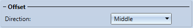
- Under Offset you select to which side the sheet thickness (material thickness) is to be removed.
|
Middle |
The material thickness is applied equally to both sides of the composite edge. |
|
First side |
The material thickness is applied to the "outer" side. |
|
Second sideSeite |
The material thickness is applied to the "inner" side of the sketch. |
Bend zone runout
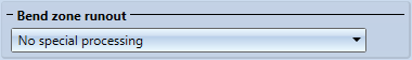
- Here you specify the Bend zone runout.
|
|
No special processing |
Bend zones that meet in a corner of the sheet are shortened to avoid overlapping. |
|
|
Flush |
If several bend zones converge in one corner, the sheet is widened in the corner to make room for the bend zones. The front surfaces of the bend zones are flat surfaces. They are not adjusted to the adjacent flanges.. |
|
|
Flush and corrected |
If several bend zones converge in a corner, the sheet is widened in the corner. The front surfaces of the bend zones are adjusted to the adjacent flanges. |


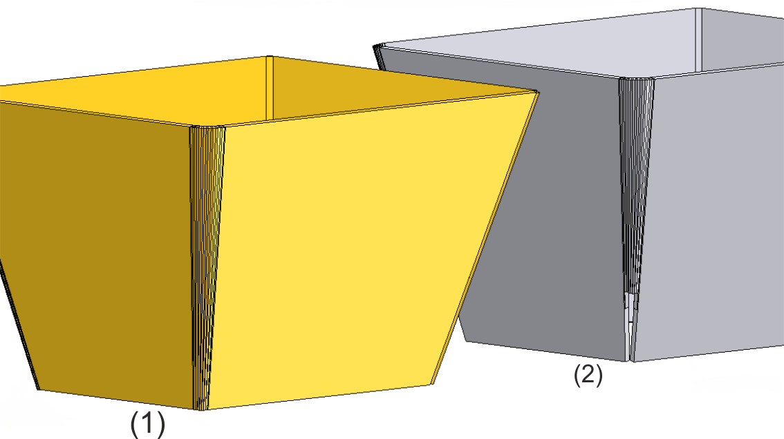
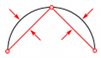
(1) Flush and corrected
(2) No special processing, not flush
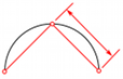
Accuracy criterion
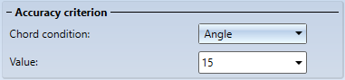
- Enter the Accuracy criterion ein.
The arcs of the composite edges (guidelines) are approximated synchronously by polygons so that two lines lie in one plane and thus define a flange. You define the accuracy of the resulting sheet metal flanges in the Accuracy criterion area.
|
|
Angle |
The value determines the maximum angle at the corner between two flanges. The smaller the angle, the finer the approximation. |
|
|
Distance |
The entered value determines the maximum distance between the flange and the composite edge (guideline). |
|
|
Length |
The maximum width of a flange resulting from the approximation is specified here in millimetres. |

General
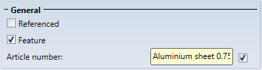
- Activate the Referenced checkbox if the part should be saved as referenced (see HiCAD 3-D).
A frequently used part should be saved as referenced. The part is then additionally saved as a single part at the end of the function sequence and is not permanently integrated into the drawing. If the individual part is changed, you can update the part in the drawing.
To deactivate the feature when creating the sheet metal part, deactivate the checkbox ![]() . By default, the feature technology is active
. By default, the feature technology is active ![]() .
.
If the Article number checkbox is activated ![]() and you have also activated semi-finished products, the Article number is loaded from the catalogue. The catalogue column is adjustable. If you have not activated the checkbox, you can enter any Article number.
and you have also activated semi-finished products, the Article number is loaded from the catalogue. The catalogue column is adjustable. If you have not activated the checkbox, you can enter any Article number.
Apply/discard inputs
- To create the connection, exit the input window with OK, for example.
Once you have entered all the necessary data, the connecting sheet can be installed as shown in the preview. If you select Apply or press the middle mouse button, the flange is inserted, but the dialogue window remains open - in contrast to OK. This way you can change the data and assign it to other sketches with Apply. If you leave the dialogue window with Cancel, the function is cancelled without installation or modification
![]() Please note:
Please note:
Incorrect inputs are marked with the  symbol. Move the cursor over the symbol to display an error description.
If the function cannot be executed with the entered data, the info symbol  appears at the OK button. Move the cursor over the symbol to display an error description.
Example
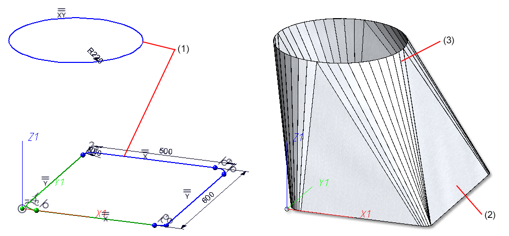
(1) First and second guideline in a 3.D sketch
(2) Connecting sheet
(3) Accuracy criteria: Angle 5
