HiCAD has libraries of bore patterns (e.g. Agrafes) and punches. To expand the libraries you can use
- 2-D parts that could be parameterized with the 2-D HCM (file format: .DCF) or
- planar sketches that can be parameterized with the Sketch HCM (file format: .KRA)
(please also see Bore Patterns in 3-D).
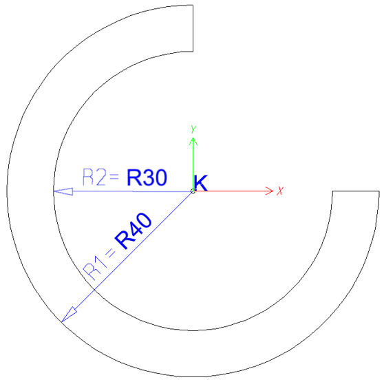
The following example uses the contour shown below as a bore pattern in different sizes.
Example 1: Create 2-D part > Parameterize > Add bore pattern to catalogue > Insert new bore pattern > Bore pattern in development

Example 1
Step 1: Create 2-D part
- Open the 2-D Part tab and choose New > New main part
 to create an empty 2-D part, e.g. 001_0001.
 - Select 2-D Geometry > Grid
 > Point grid ON
 and specify a X- and Y-distance of 10.
 - Draw a 3/4 circle with the function Arc, CP-P-P

 with a size of 30, and another circle with a size of 40 with the same centre point.
 - Connect the circles horizontally and vertically with the Polyline
 function.
 - Place an isolated point into the centres of the circles via Tools > New point
 .
. - Move the 2-D part to the origin. Right-click the part name (Ring01) in the ICN. In the context menu, choose the Move part, Sketch
 function beneath Transform. Then, select the isolated point and move it to the absolute point (0, 0).
Step 2: Parameterize
- Clear the variables memory via Information > 3-D, Further > Var. > Delete variables
 .
. - Switch to the 2-D Part Ribbon.
- Specify the parallelism constraints: Choose 2-D HCM Constraints > Coinc. > Concentric
 and identify the two circles.
 - Then, choose ... Distance > Radius
 to assign the positional constraint to the elements. Identify the outer circle, enter R1 instead of a value input, and 40 as the variable for R1. Identify the inner circle, enter R2 and 30 as the variable.
- Save the HCM model with 2-D HCM Constraints > Edit > Without database
 (2-D Part > 2-D HCM Constraints) e.g. with the name 001_0001. Select the HiCAD folder KATALOGE/WERKSNORMEN/MUSTERBOHRUNGEN as storage location.
 -
To display the bore pattern during installation, save a screenshot of the bore pattern under the name 001_0001.jpg in the HiCAD folder KATALOGE/WERKSNORMEN/MUSTERBOHRUNGEN/IMAGE using an image editing program. Enter the path in the catalogue in the ICON column.
Step 3: Add bore pattern to catalogue
- Start the CATEDITOR.EXE
 program in the HiCAD EXE directory.
 - Open the Bore patterns directory. Choose Extras > Table > New to create a new table for the bore pattern, e.g. 001_0001.
- Select the Category 2-D pattern. Confirm with OK.

- The new table contains the columns ID, MOD, STATUS and BZ.
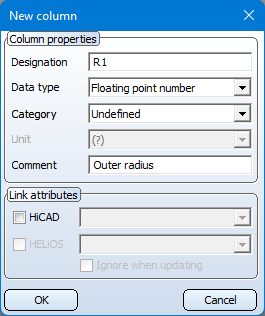
- Now add further columns by right-clicking the column header of the BZ column and selecting New column.
- Enter the name of the variable in the Designation field, e.g. R1. In the Data type Floating point number. The text in the Comment field will be shown as tooltip. when you move the cursor over the column header. Enter, e.g., Outer radius here.
- Create another column (R2, Floating point number, Inner radius) for the variable R2.
- Create a column with the Designation: TOPSYMBOL, Data type: Text and Comment: Symbol from top for the symbol in the development.
- Create another column with the Designation: BOTTOMSYMBOL, Data type: Text and Comment: Symbol from bottom for the symbol in the development.
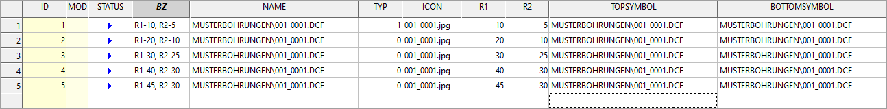
- Now create the data records.
- To do this, right-click in the first row on the left and select New record.
- Then double-click in the new row in the columns BZ and enter the name that is to be displayed in HiCAD during the later selection, e.g. R1-10, R2-5.
- Enter the relative path of the parameter variant (MUSTERBOHRUNG\001_0001.dcf) in the NAMEcolumn.
- For ICON, enter the name of the JPG file001_0001.jpg) ein.
- Then enter the values for the variables R1 and R2 ein.
- For the symbol in the development, enter the relative path and the HCM model (MUSTERBOHRUNG\001_0001.DCF) in the columns TOPSYMBOL and BOTTOMSYMBOL .
- Create further data records with variables for R1 and R2 and save the table (File > Save).
Step 4: Insert new bore pattern
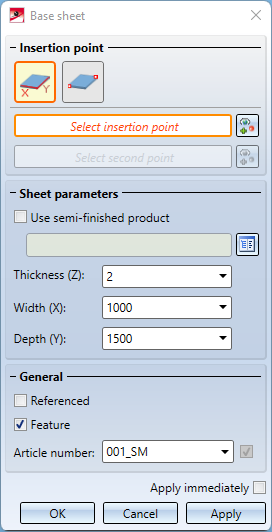
- Create a new base sheet in HiCAD: On the Sheet Metal tab, choose New > Create base sheet
 . Enter the desired dimensions in the dialogue window, e.g. Width 1000, Depth 1500 and Thickness 2. Then select the two fitting points for the base sheet in our drawing by right-clicking and selecting the Origin option. Confirm with OK.
- First, activate the Sheet Metal flange that is to be processed, then select the Bore pattern
 function (3-D Standard > Standard Processings > Bore > ...).
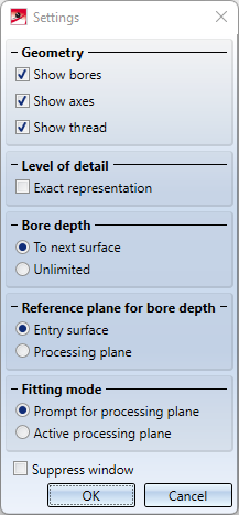
 - Activate the required options in the Settings dialogue for the bores and confirm with OK. Choose Through for the processing of several flanges and Prompt for processing plane.
- Activate 2 edges of the base sheet to define the processing plane.
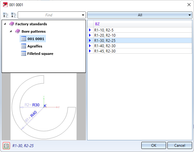
- In the selection window, choose the bore pattern 001_0001. The variants will be shown on the right hand side. After selecting a variant, e.g. R1-30, R2-25, click OK.
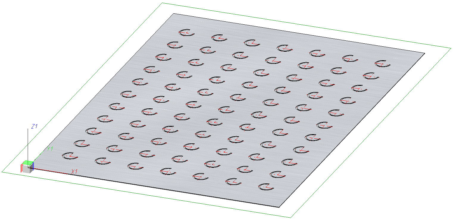
- Select a Grid
for insertion. Click the Linear
 button and enter the number of bores in X- and Y-direction, e.g. nx: 7 and ny: 11 an. For the distance in X-direction enter dx: 130 and click the
  icon to apply the same value to all bores in X-direction. For the distance in Y-direction enter dy: 120. Here, too, click the icon.

The fitting grid determines the distance of the bores in X- and Y-direction, respectively. The value can be specified individually for each row/column.
- Position the tool using the point options. Open the point options window with Return. Choose Relative
 and, in the displayed pocket calculator window, click OK. Identify the upper left corner of the sheet. The pocket calculator will then prompt you to specify the X- and the Y-value. Enter 500 for X, 750 for Y and 0 for Z and confirm with OK.
You can then insert the bore again, change the parameters via right-click, or end the function by pressing the middle mouse button.
Step 5: Bore pattern in the development
- Select the Develop sheet
 function.
 - Select an edge of the sheet and activate the Outer contour option under Dimensioning.
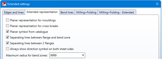
- Open the Extended settings
 dialogue window. There, open the Extended representation tab.
 - Activate the option
 Planar symbol from catalogue.
- Close the Extended settings dialogue with OK.
- Place the development in the drawing and exit the dialogue with OK.
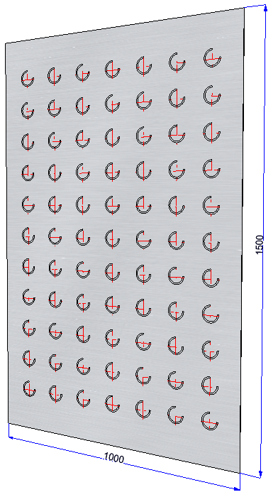
The bore pattern is displayed as a symbol in the development.
