
Determining the part orientation
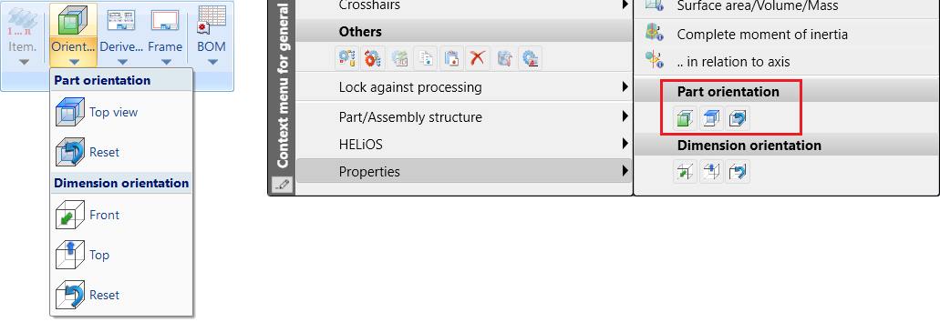
Drawing > Itemisation/Detailing > Orient...
Right mouse button > Properties > Part orientation
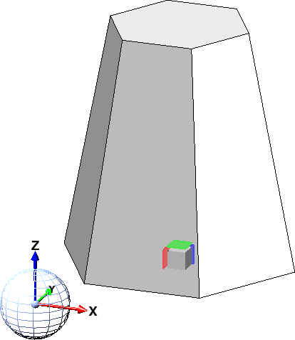
In HiCAD, each part has a specific orientation during insertion - the part orientation. This is visualised - if set in the Configuration Editor - on the part by the symbol of a cube.
The part orientation is determined according to the following priorities:
- The orientation is set manually via the functions under Properties > Part orientation in the context menu for parts and assemblies or in the context menu for 3-D parts and assemblies under Properties.
- The orientation results from the processing direction.
- The orientation results from the bearing bar direction. This only applies to gratings according to DIN 24537.
- The orientation results from the part coordinate system.
The first option that is available is used. Therefore, since each part and assembly has a part CS, there is always a usable orientation and the dimensions can be calculated.
For assemblies with an assembly main part, the following applies: If the orientation for the assembly has been set manually, this orientation applies. If no orientation has been set manually for the assembly, the orientation of the assembly main part will be adopted. The above sequence applies.
Whether the dimensions are visualised in the drawing depends on the setting in the Configuration Editor under System settings > Visualisation > Show dimensions of the active 3-D part.
If the dimension display is active, the dimensions will be displayed in the form of a cube. Green stands for the front view, blue for the top view. In addition, a symbol indicates the source of the orientation.
If the assembly or the view is rotated, the annotation of the parts will be adjusted accordingly.
|
Meaning of the annotations |
|
|---|---|
|
|
The orientation corresponds to the part coordinate system. |
|
|
The orientation results from the bearing bar direction (only for gratings DIN 24537). |
|
|
The orientation results from the processing direction. |
|
|
The orientation was set manually. |

|
The orientation results from the part coordinate system of the assembly main part. |

|
The orientation results from the bearing bar direction of the assembly main part (only for gratings DIN 24537). |

|
The orientation results from the processing direction of the assembly main part. |
|
|
The orientation of the assembly main part was set manually. |


The part orientation assigned to a part is saved with the part.
Manually setting the dimension orientation
In practice, it can sometimes be useful to manually specify which view of the part is to be considered as the front view or top view when deriving drawings. You can set the orientation manually under Drawing > Orient... > Part orientation or in the context menu for 3-D parts and assemblies under Properties. Multiple selection of parts is also possible.
With the functions under Drawing > Orient... > Part orientation, the part orientation of multiple parts can be set or reset one after the other without having to call the function again.
After calling the Front view or the Top view function, first select the part whose orientation you want to change and then the desired plane for the front view or the top view. To determine the plane, you have to select the corresponding plane. The same functions (right mouse button) are available for the determination of the plane as for the determination of processing planes. If the dimension alignment display is also active, the enveloping cube and the orientation symbol will be updated immediately. You can then change the orientation of further parts or correct the orientation directly by selecting the previously selected part again. You can terminate the function with the middle mouse button.
The corresponding functions in the context menu apply only to the active part and are automatically terminated.
This setting influences the orientation of parts in derived drawings as well as the pipelines in isometries and pipe spool drawings. In addition, the orientation is also considered when calculating assembly dimensions.
If you want to undo the selected part orientation, select the Reset  function.
Example:
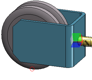
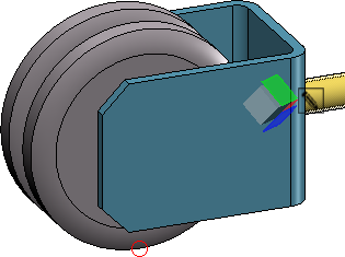
In the following image, the part orientation of the prism has been changed. On the left, plane (1) has been selected as the top view, and on the right, plane (2) has been selected as the front view.
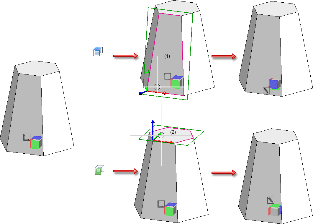
If the original part orientation is changed, this is indicated by  on the symbol.
An example of the effects on derived drawings can be found here.
|
Please note: Parts with the same item number have the same part orientation. In detail, the following procedure is used:
|
![]() Please note:
Please note:
-
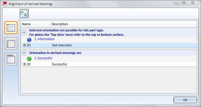
For beams and plates, when you call one of the Define front view or Define top view functions, the system will check whether the new orientation is actually allowed.
Please note the following:
- Top views of plates must be perpendicular to the upper or lower plate side!
- Front views of beams show either the front side or the rear side of the web.
- Front views of round profiles must run horizontally, while allowing a free rotation about their axes. This enables a rotation of the view-defining coordinate system for trimmed round beams in such a way that the cutting angle can be dimensioned in the workshop drawing.
The result of the check will then be shown in a dialogue window. Here it will be listed for which of the chosen plates the new orientation was successful, and to which no new orientation could be applied.
Use the symbols on the left to switch between the following representations of the list:
 Detailed list
 Abridged list
 List with several tabs
Click the  symbol to save the result list as a CSV file.
- Since no workshop drawing can be created for sheet metal flanges and bend zones, the orientation always refers to the main sheet metal part. Orientations of sheet metal flanges and bend zones that were set in older HiCAD versions (before 2020 SP1) can be deleted using the Reset function. The main sheet metal part must be active. The view orientation of the sheet metal main part is displayed for these sheet metal straps and bend zones.
Settings in the Configuration Editor
The visibility of the marking can be switched on or off via the settings in the Configuration Editor at System settings > Visualisation > Show orientation of active 3-D part in drawing:
- Never
The marking indicating the orientation is never shown. - Always
The marking indicating the orientation is always shown (provided that an orientation has been specified). - Switch on/off with F6 key
The marking indicating the orientation can be shown or hidden with the F6 key. This is the default setting. If this setting is active, the orientation marking can also be shown/hidden via the Coordinate systems toolbar (at the bottom of the dialogue window) by clicking on the icon.
icon.

Part Properties (3-D) • Surface, Line ans Edge Parameters • Colour Editor • Model and Process Parts (3-D) • Derived Drawing - Active View as Front View/Top View