Edit Export Settings
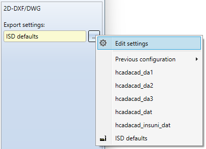
In the export dialogue for 2-D DX/DWG files you can call up an extended dialogue window for the export configuration via Export settings > ... > Edit settings to open an extended dialogue window for the export configuration.
The Export Settings 2-D DXF/DWG dialogue window consists of the following tabs:
![]() Please note:
Please note:
All options in the dialogue refer to both 2-D DXF and 2-D DWG export. If, for the sake of clarity, only "DXF" is written in the dialogue, for example in the tab designations, the DWG format is implicitly included.

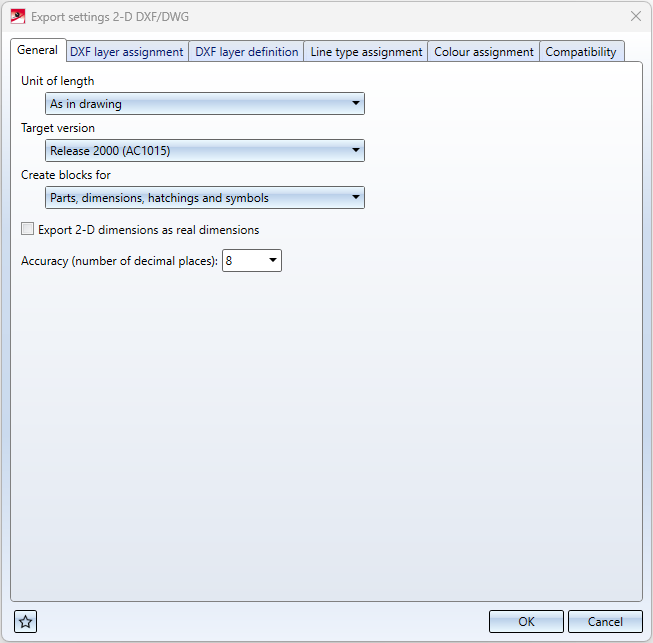
General
|
Unit of length |
These options can be used to control the unit in which the data is to be transferred to the DXF file. The header variable of the DXF file ($INSUNITS) is then set according to this unit. The default setting As in drawing transfers the data according to the HiCAD drawing unit. In addition to the selection options Millimetre, Centimetre, Decimetre, Metre, Inch and Foot that can be set as export unit, you also have the option here in the pull-down menu to set the transfer to Unitless. In this case, the data will be exported in HiCAD units, but the header variable will be set to "unitless" ($INSUNITS = 0). |
|
Target version DXF |
This option can be used to set whether the DXF file is to be exported in Release 2000 (AC1015) or Release 12 (AC1009) DXF format. By default, the DXF file is written in the version Release 2000 (AC1015). (This option replaces the former setting option "ACDXF" in the corresponding configuration file as of HiCAD 2023 Service Pack 1). |
|
Create blocks for |
Here you can determine with a corresponding puldown menu selection whether blocks for
are to be created. (This option replaces the former setting option "FIGBL" in the corresponding configuration file as of HiCAD 2023 Service Pack 2).
This setting may conflict with the "FIGLA" setting from the Compatibility tab: FIGLA 1 can only be used if no blocks are created for parts. |
|
Export 2-D dimension as real dimensions |
This checkbox can be used to determine whether 2-D dimensions are to be transferred to the DXF file as dimension objects (DIMENSION), or only as geometries and texts. 3-D dimensions are always transferred as geometric dimensions. By default, 2-D dimensions are transferred as geometries and texts. (This option replaces the former setting option "BEMAS" in the corresponding configuration file as of HiCAD 2023 Service Pack 1). |
|
Accuracy (number of decimal places) |
Here you can specify how many decimal places are transferred to the DXF file. By default 8 decimal places are transferred. The maximum value for the number of decimal places is 14. (This option replaces the former setting option " NKST" in the corresponding configuration file as of HiCAD 2023 Service Pack 1). |
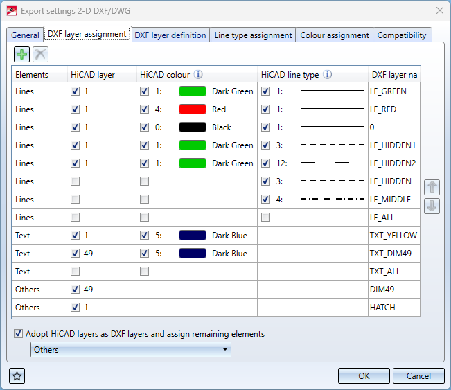
DXF layer assignment
Using the table in this dialog tab, HiCAD Elements (lines, texts, other) can be assigned to corresponding DXF layers (DXF layer name) via their properties HiCAD layer, HiCAD colour and HiCAD line type.
Examples:
-
In the first line, all HiCAD elements of type Lines that have HiCAD layer "1", HiCAD colour "1" (dark green) and HiCAD line type "1" (solid) are assigned to DXF layer "LE_GREEN" in the DXF layer name column.
-
In the sixth row from the top, all Lines with HiCAD line type "1" (solid) are assigned to the DXF layer "LE_HIDDEN" regardless of their layer and colour.
For HiCAD elements of the type Text the HiCAD line type is not relevant, for elements of the type Others HiCAD color and HiCAD line type are not relevant.
Others includes the elements Dimensions, Hatchings, Symbols and also Texts, if these have not been assigned before via Elements.
If the checkbox in a cell is activated, then the corresponding property of the element is taken into account.
The default properties of the DXF layer specified as DXF layer name can be configured via the DXF layer definition tab (see below).
At the bottom of the window, under this tab, you will find the pull-down menu item Adopt HiCAD layers as DXF layers and assign remaining elements.
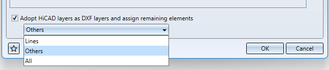
Here you can determine whether DXF layers should be created for unassigned elements (according to their HiCAD layer), and if so, for which type of elements:
-
Lines
-
Others (contains HiCAD texts)
-
All
The elements will then be assigned to the corresponding DXF layers.
If the checkbox is not activated, then all remaining elements will be assigned to DXF layer "0".
![]() Important:
Important:
The layer assignment is only performed if the keyword "FIGLA" in the Compatibility dialogue tab is set to 0 (this is the default setting for the keyword). If FIGLA is not 0, the options of this tab have no effect.
(This options dialogue replaces the former keyword settings "LAYER", "TXTLA" and "SONST" in the corresponding configuration file as of HiCAD 2023 Service Pack 2).
DXF layer definition
The table in this area can be used to configure the color (DXF color index), the line width and the line designation (DXF line type) for DXF layers. The DXF layers are transferred to the DXF file with their names and the selected properties (LAYER table).
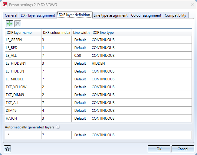
Independent of this configuration of the default values to the layers, DXF elements can also have their own DXF color, line width and line type.
For all other layers automatically generated during export, the properties of the bottom row Other layers are used.
![]() Important:
Important:
Each DXF line type listed there must also appear on the Line type assignment dialogue tab!
(As of HiCAD 2023 Service Pack 2, this option replaces the former keyword setting option "BYLAY" in the corresponding configuration file).
Line type assignment
Auf diesem Reiter wird jeder HiCAD-Linienart eine DXF-Linienart zugeordnet. Die DXF-Linienart besteht dabei aus einem Namen (Spalte Name der DXF-Linienart) und einer Beschreibung.
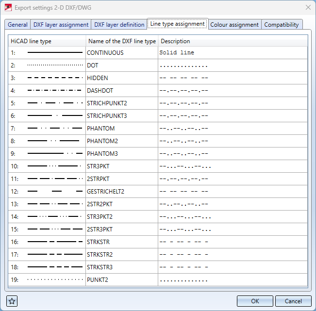
( Diese Option ersetzt ab HiCAD 2023 Service Pack 2 die frühere Schlüsselwort-Einstellungsmöglichkeit "LTDEF" in der entsprechenden Konfigurationsdatei.)
Colour assignment
The table in the Colour assignment tab contains an assignment of HiCAD colors to DXF color indices:
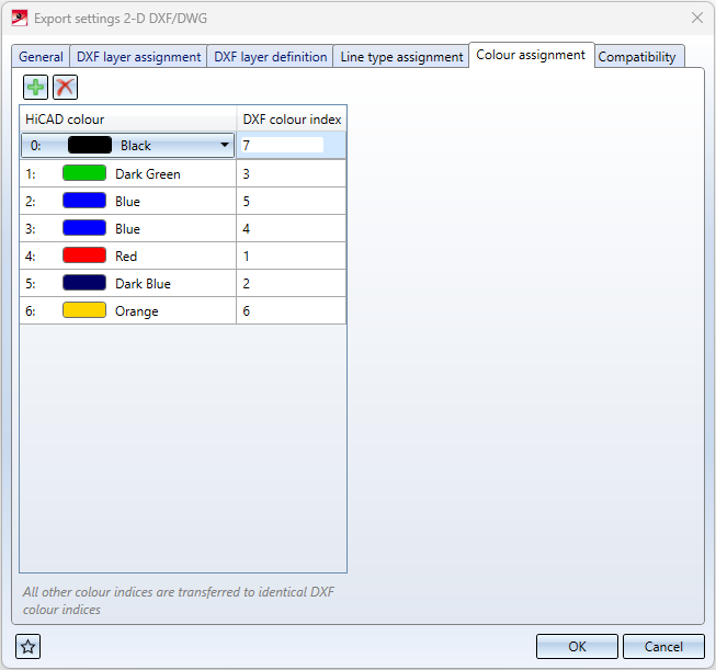
In the dialogue window, new rows can be added by clicking on  , or rows can be deleted by selecting them and clicking on
  .
.
If a HiCAD colour is not listed in this table, the assignment is as follows: The index by which the colour is represented in the DXF file corresponds to the original HiCAD colour index +1.
(This option replaces the former setting option "COLOR" in the corresponding configuration file as of HiCAD 2023 Service Pack 1).
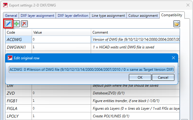
Compatibility
In the Compatibility tab of the Export Settings dialogue you will see a list of all set configuration Codes, their respective Values and a Comment line.
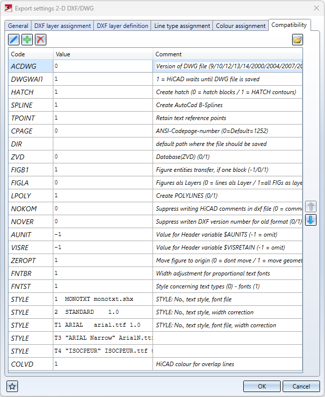
The settings include:
- the assignment of the HiCAD elements to certain DXF-layers,
- the assignment of the HiCAD line types to the DXF line type,
-
the correspondence between the symbols in HiCAD and the DXF blocks and
- the determination whether a complete DXF file including HEADER section, TABLES section etc. is transmitted or only an ENTITIES section.
Comment lines traditionally start with #.
These settings can be adjusted individually. You can change a Value by clicking in the corresponding field and changing it manually.
You can edit an entire row including Code and Comment by selecting it and clicking on the pen symbol at the top left of the dialogue.
You can load the configurations from older system files (hcadacad.dat) by clicking on the  symbol at the bottom of the window and selecting a corresponding one in the following selection dialogue.
Clicking on the  symbol at the bottom left opens the Favourites menu.
The first 5 characters always contain one of the following keywords:
|
ACDWG |
The DWG format corresponds to the DXF format; a format output changed from DXF can be done by entering the number for the DWG version ACDWG nr |
|
HATCH |
Hatching transfer is possible under the following conditions:
With HATCH 0 the transfer is switched off, default is 1. |
|
DIR |
Directory path into which the DXF files are to be copied |
|
ZVD |
If the module Central Management Database is available, the creation of DXF files is managed via the database |
|
FIGLA |
Determines whether parts are transferred to LAYER |
|
BLOCK |
Assignment of HiCAD parts and DXF blocks (only relevant if TABLES-Section is created) |
|
ZEROPT |
If "ZEROPT" is entered in HCADACAD.DAT and only the active 2-D part is exported to DXF (e.g. automatically with sheet metal and WINISO), the following applies:
The default, if the entry is missing, is ZEROPT 0. The default in HCADACAD.DAT is "ZEROPT 1". |
|
LTYPE |
Assignment of a HiCAD line type to the DXF line type, if this differs from the line type of the layer |
|
LPOLY, NPOLY |
Control of the use of POLYLINES |
|
NOKM |
Definition of HiCAD comments |
|
STYLE |
Definition of a text style |
|
THICK |
Assignment of additional numerical information for the lines of individual parts |
|
BEMAS |
Control of the dimension transfer |
|
NKST |
Decimal places (max. 14) |
|
AKNIT |
Control flag for ACAD variable $AUNITS |
|
NOVER |
Suppress DXF version number |
|
FNTBR |
Width adjustment for text fonts |
|
COLVD |
HiCAD colour for overlap lines |
|
ASCII |
HiCAD to DXF (special) character conversion |
|
FNTST |
Evaluation of style with regard to text types |

Create 2-D DXF/DWG File • Keywords • 2-D DXF/DWG Settings • 2-D Interfaces