Plant Engineering > Pipeline Tools > Change  > Calculate transition
In practice, it is often the case that two pipelines have to be connected by means of suitably cut bends, as in the following example.

To solve this problem, use the Calculate transition function.
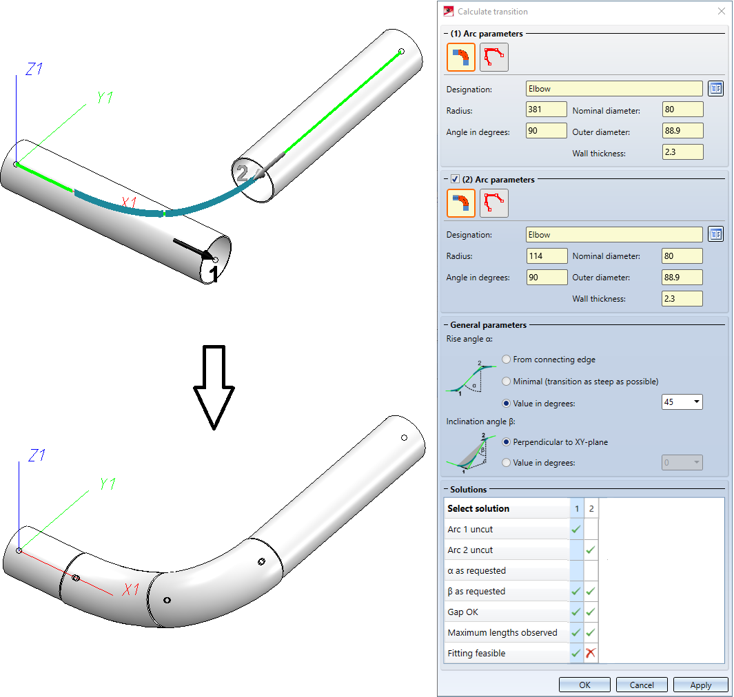
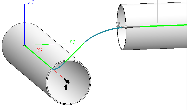
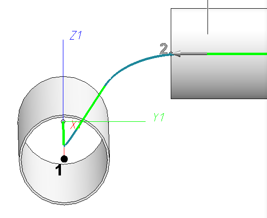
After calling the function, the Calculate transitions dialogue window will be displayed. While this dialogue is displayed you can select two connecting points in the model drawing. Clicking on a connecting point again deselects it. The connecting points are marked with (1) and (2) here. The dialogue, which is divided into four areas, also refers to these designations:
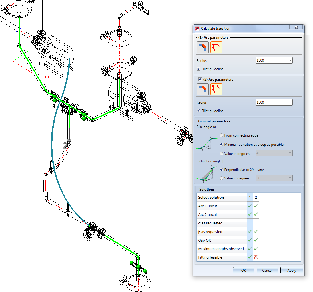
| (1) Arc parameters |
Here you parameterize the first arc, i.e. the arc with the connecting point 1. |
| (2) Arc parameters |
Here you parameterize the second arc, i.e. the arc with the connecting point 2. |
| General parameters |
In this section you can specify additional conditions that a solution should comply with if possible. |
|
Here all solutions found are listed in a table. For each solution the table lists different properties. |
![]() Please note:
Please note:
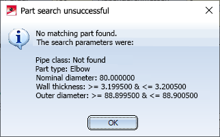
- If the part search fails, a corresponding message is displayed. The part search uses as search parameters values from the selected connections, namely those that you have defined for Elbows on the Part search tab of the Plant Engineering Settings dialogue window. The pipe class is also taken into account. If no suitable part is found, a corresponding message is displayed:
- If you have selected a solution that cannot be placed or if an entry is incorrect, this is indicated by the
 symbol on the OK button. If an entry is incorrect, the respective field is marked with the
  symbol. If you move your cursor over one of the symbols of the symbols, further information will be displayed.

Arc parameters
The areas (1) Arc parameters and (2) Arc parameters support two modes:
- Insert arc element and
- Insert guideline.
Use the  and
and  symbols to switch between the modes.
|
Insert arc element |
|
In this mode you define an arc by selecting it directly from the database or catalogue. You can do this via the Part search
|
|
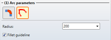
Insert guideline |
|
In this mode, you directly specify a radius. Instead of a concrete arc, only a guideline edge will be drawn. Optionally, you can also apply curves to this guideline so that it can later be used to install a bent pipe.
|


General parameters
This area is divided into Rise angle α and Inclination angle β. The pictograms for the angles are displayed larger if you move the cursor over them.
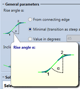
Rise angle α
The rise angle α affects how the arcs are cut to form a transition.
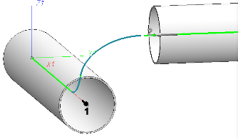
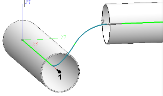
The From connecting line option determines a rise angle from any existing connection between the two connection points. The connection can be a guideline or a pipe, for example. If several sections between the connecting points are possible, the longest section will be chosen. In the following image you can also see how a gap between the pipe bends is created by defining the rise angle. In the concrete example, this gap is shown in red because it violates the specifications for minimum lengths.

The Minimal (transition as steep as possible) realizes a transition that is as steep as possible.

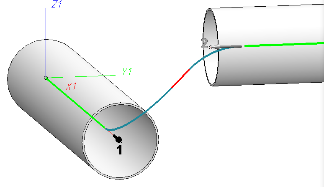
Finally, you can also specify a particular angle yourself using the Value in degrees option. The reference axis of the angle is the Z-axis of the active coordinate system, provided that it is not collinear with the direction at Connecting point 1. In the following image , for example, by specifying an angle of 45°, the gap between the arcs becomes large enough for the set minimum lengths:

Inclination angle β
The inclination angle β is only relevant for skewed transitions. It determines how much an arc is rotated around the axis through the connecting point. The angle again refers to the Z-axis of the active coordinate system.
The option Perpendicular to XY-plane means that the arc should be installed as steep as possible. The Value in degrees option allows the specification of a concrete value.
Below you can see a comparison with different values for β:
|
Perpendicular to XY-plane |
Value in degrees: 30 |
Value in degrees: 45 |
Value in degrees: 60 |
|
|
|
|
|

If you combine the rise angle α and inclination angle β you can therefore create transitions that are inclined in both respects with regard to the Z axis.
Below you can see an example with α=45° and β=30° from three different perspectives:
|
Perspective oblique from the front |
Perspective with clearly recognizable α |
Perspective with clearly recognizable β |
|
|
|
|

Solutions
In this area you will find a table in the columns of which all solutions found for the transition have been entered. The cells of the table can either be empty, contain a green tick or a red cross. Columns containing a red cross cannot be created. However, you can display such solutions in the preview. This usually makes it clear where the generation fails.
The solutions are characterized by the following properties:
|
Arc 1 uncut
|
empty |
The arc needs to be cut. |
|
|
The arc can be fitted without being cut. |
|
|
|
The angle of the selected arc is too small. |
|
|
Arc 2 uncut |
|
like Arc 1 |
|
α as requested |
|
The solution corresponds to the initialization value of the field Value in degrees. |
|
β as requested |
|
Like α |
|
Gap OK |
|
If you use weld gaps, the gap between the bends is either exactly one gap width or two gap widths plus minimum length of a straight pipe. If you do not use weld gaps, only the minimum length of a straight pipe will be considered. |
|
Maximum lengths observed |
|
Due to the fitting of a bend no maximum lengths are violated |
|
Fitting feasible
|
|
The adjoining parts can be adapted so that the transition can be fitted. |
|
|
The adjoining parts do not allow the transition to be fitted. |

Fitting
If you click OK or Apply, the transition will be implemented. In general, a transition consists of bends, weld seams and guidelines. For the installation to be successful, it must be possible to move the selected connecting points appropriately. For this purpose, a route change will carried out internally on the adjoining pipelines or pipeline sections.
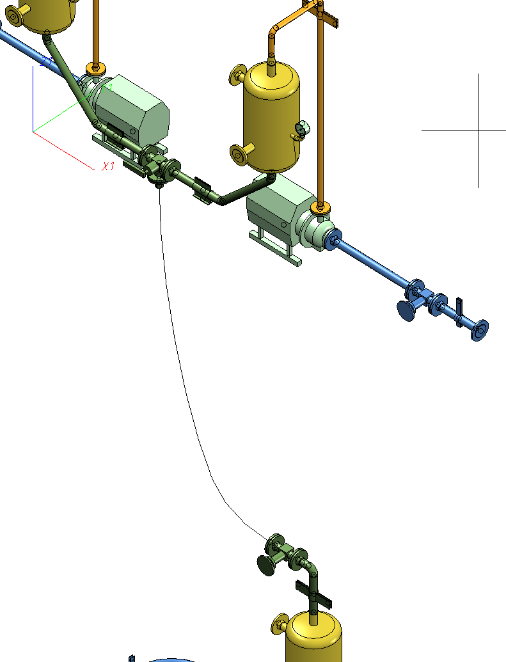
Here is an example where there could be two solutions, but the adjoining parts prevent the installation of the second solution:
|
Solution1 (Fitting feasible) |
|
|
|
Solution 2 (Fitting not feasible) |
|
|

You can see from the representation for Solution 2 that the transition could not be fitted into the pipeline (hence the red cross  in the solution table).
The installation of a transition also deletes all parts that are located between the selected connecting points. If Solution 1 is confirmed with OK, the result is therefore as follows:
All parts between the connection points were deleted and replaced with a guideline.
Note that all newly installed parts are assigned to the pipeline to which connecting point 1 belongs.
