Plant Engineering > Pipeline Tools > Change  > Change route
Two options are available for determining the start point of the route change of pipelines:
Plant Engineering point selection
When you move the cursor over the pipelines of your model drawing, all allowed points of the corresponding pipeline will be highlighted in a different colour (Special colour Marking 1). Select the desired point. In the model drawing, this point will now be highlighted (Special colour Marking 3), together with the pipeline to which it belongs.

If you now accept this point by pressing the left mouse button (LMB), HiCAD will prompt you to select the target point of the route change.

Standard point selection
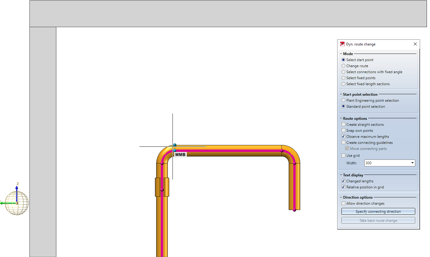
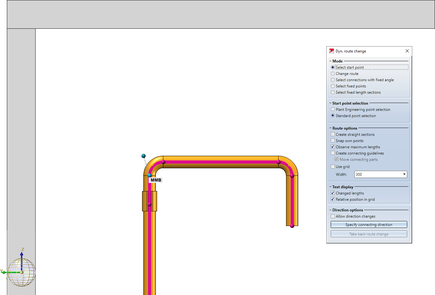
If this option is active, then you can select any point as the start point. In order to define the sections to be changed unambiguously, the route change must nevertheless refer to a Plant Engineering connecting point. Therefore, HiCAD will first automatically suggest a Plant Engineering connection point in the vicinity of the selected point and mark it with the note MMB.
- If you want to use this point as the start point, just press the LMB.
- If you do not want to use the suggested point, simply select another Plant Engineering connecting point with a left-click.
During the route change, an auxiliary line will be drawn between the point you have selected and the automatically determined or manually selected Plant Engineering connecting point. This auxiliary line is displayed in red (Special color X-axis) if the selected starting point cannot reach the target point.
Example 1
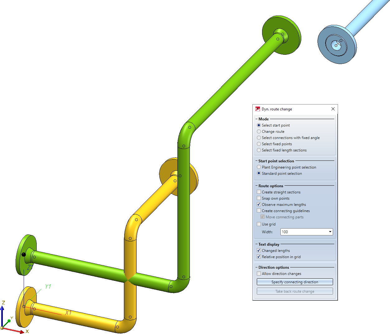
In the following example, the end points of two pipelines are to be changed while the relative position of the pipeline ends to each other is to be maintained. Specifically, the yellow pipeline is to be connected to the blue pipeline, but the end point of the green pipeline is to be moved relative to it.
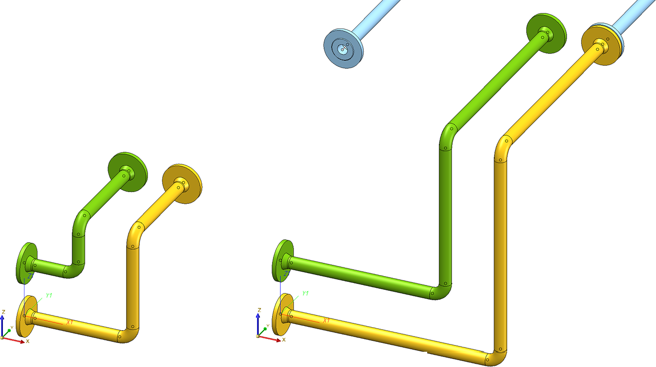
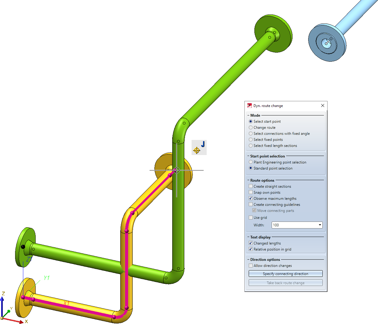
Left: Original situation; Right: Desired result
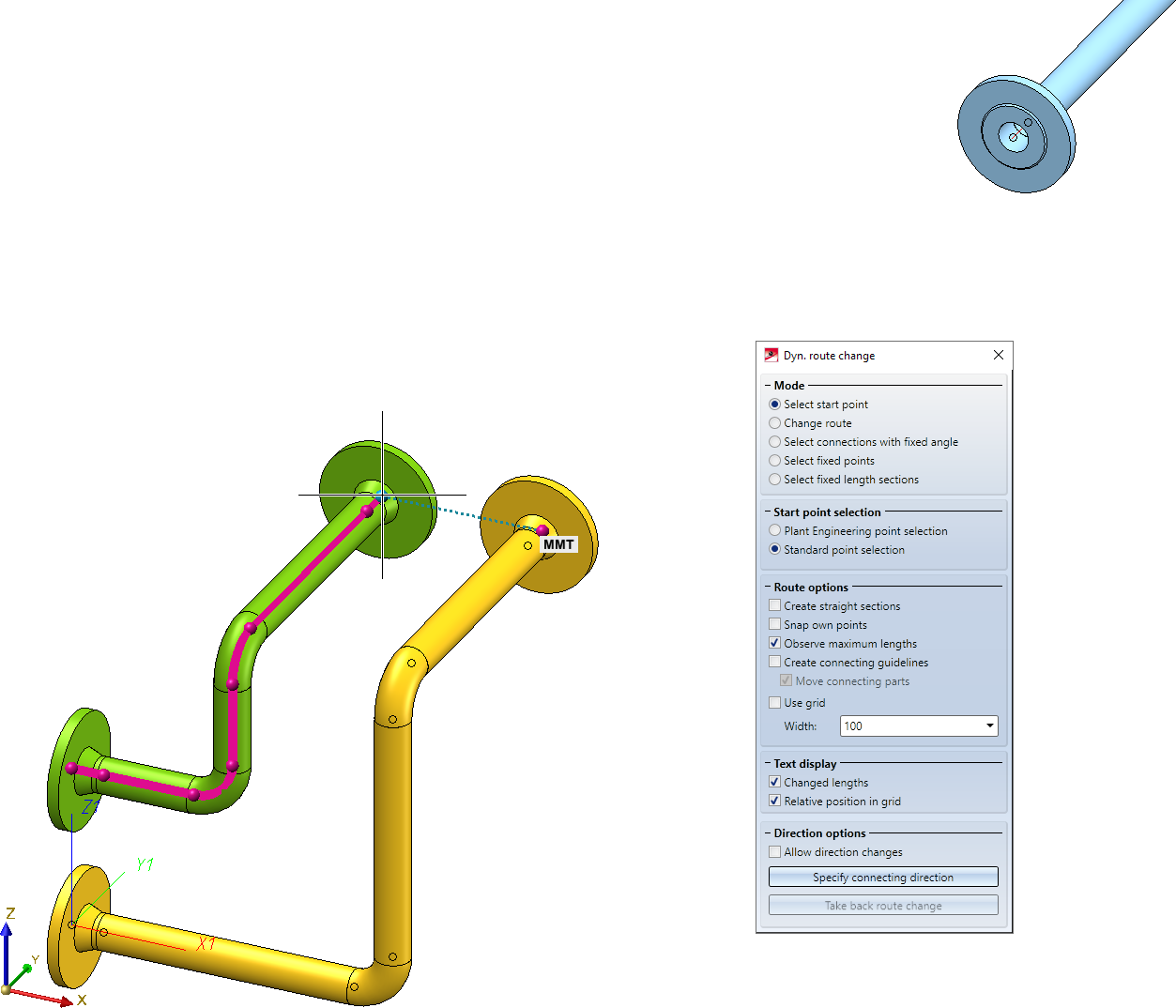
First, select the end point of the yellow pipeline as the starting point.
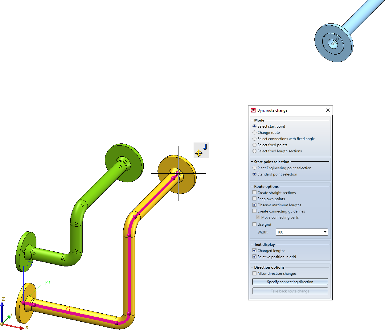
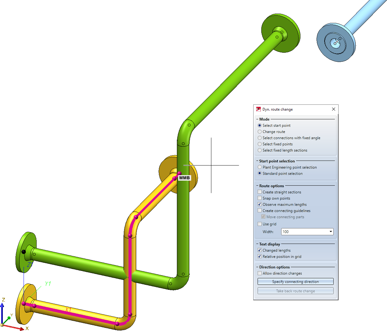
HiCAD first suggests the end point of the yellow pipeline as the suitable Plant Engineering connecting point. Instead of accepting this suggestion, select the end point of the green pipeline as the plant construction connection point. An auxiliary line visualizes the relationship between the selected starting point and the Plant Engineering connecting point.
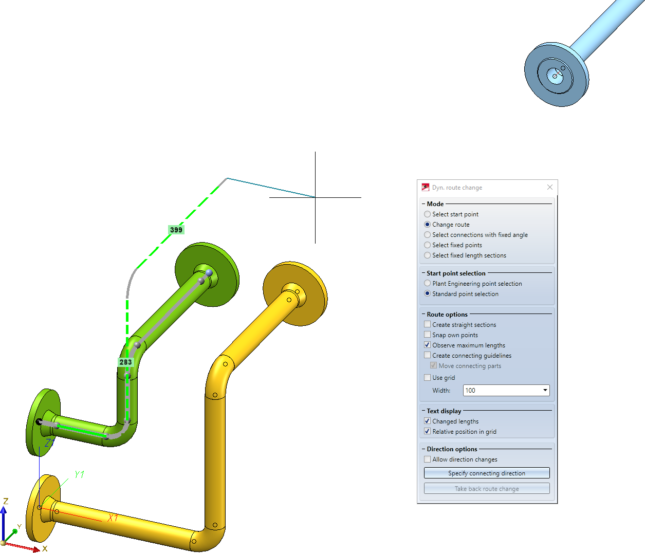
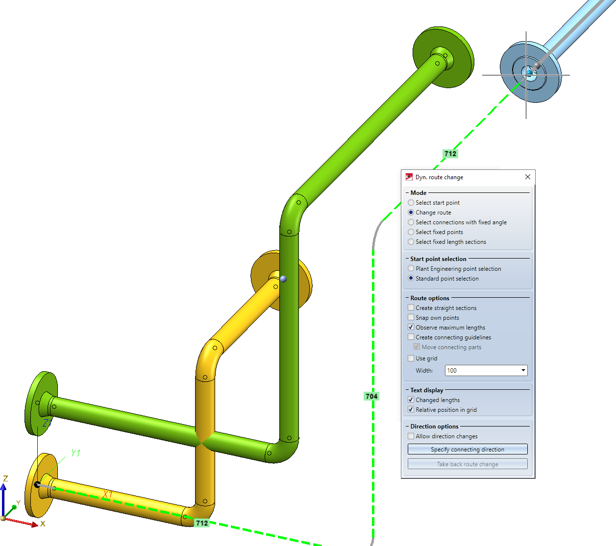
Set the starting point on the end point of the blue pipeline, which completes the modification of the green pipeline.
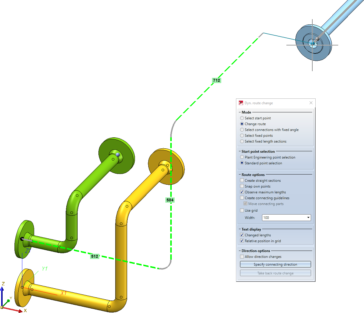
Then, select the end point of the yellow pipeline and accept as the Plant Engineering connection point by pressing the MMB.
Now, drag the selected end point into the end point of the blue pipeline and obtain the desired result.
Example 2
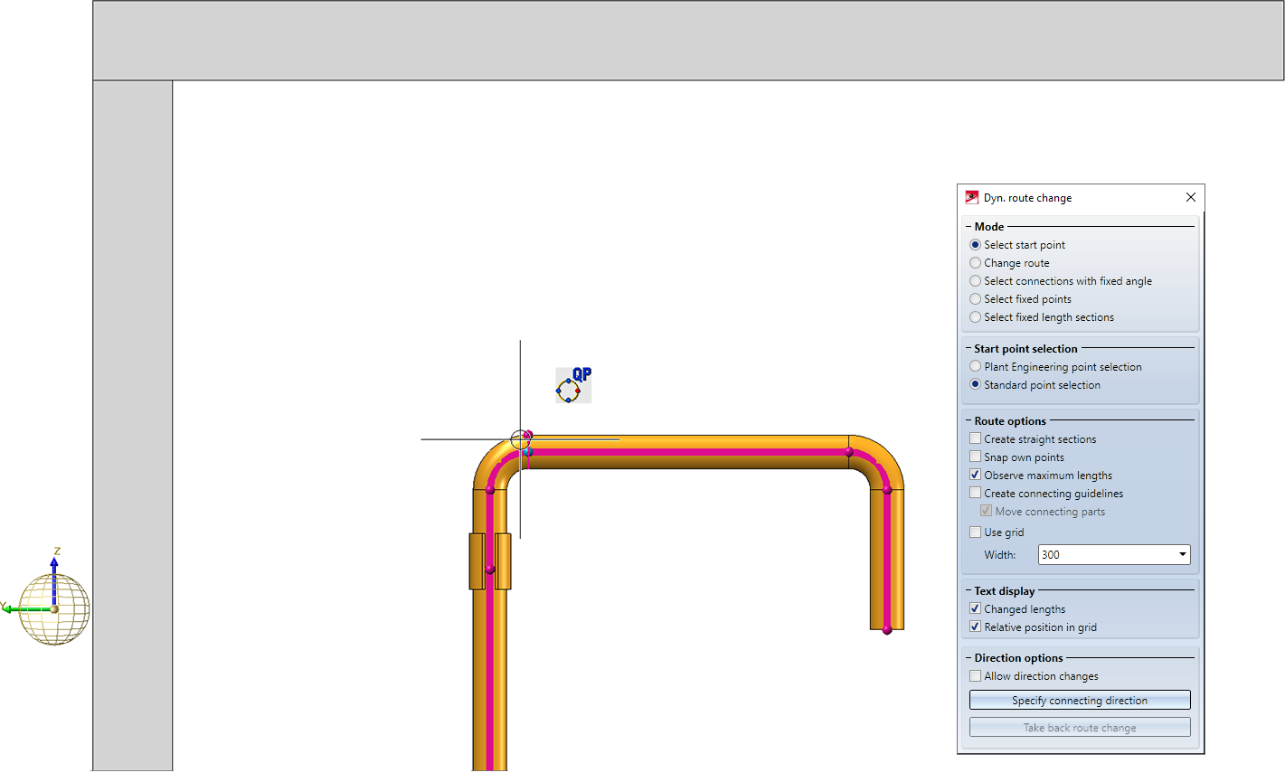
In this example, a quadrant point is selected as the start point to draw a pipe with a certain distance to a wall/ceiling.
After selecting the quad point, confirm the connecting point suggested by HiCAD with the middle mouse button.
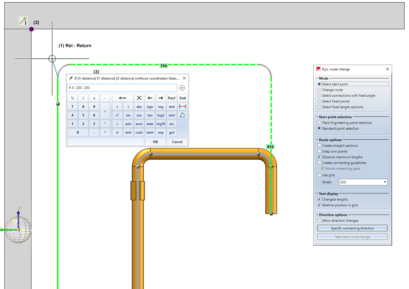
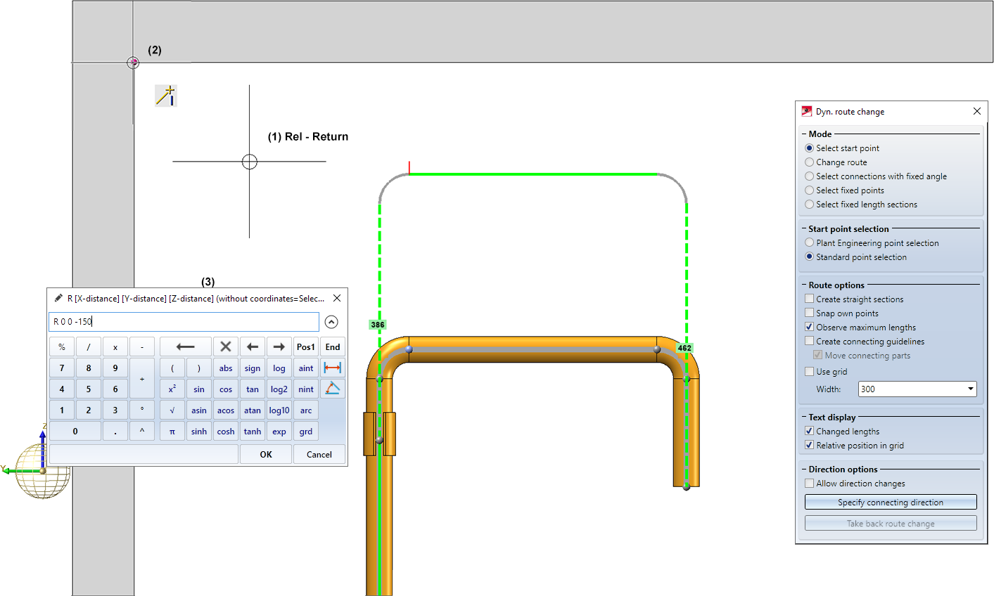
The pipeline should have a certain distance to the top. Therefore we determine the target point with Relative (R) -Return (1), select the inner corner (2) as reference point and then enter the desired distance (3).The auxiliary line between the start point and the Plant Engineering connecting point is shown in red here because the start point cannot reach the corner. However, this is irrelevant for the situation in this example.
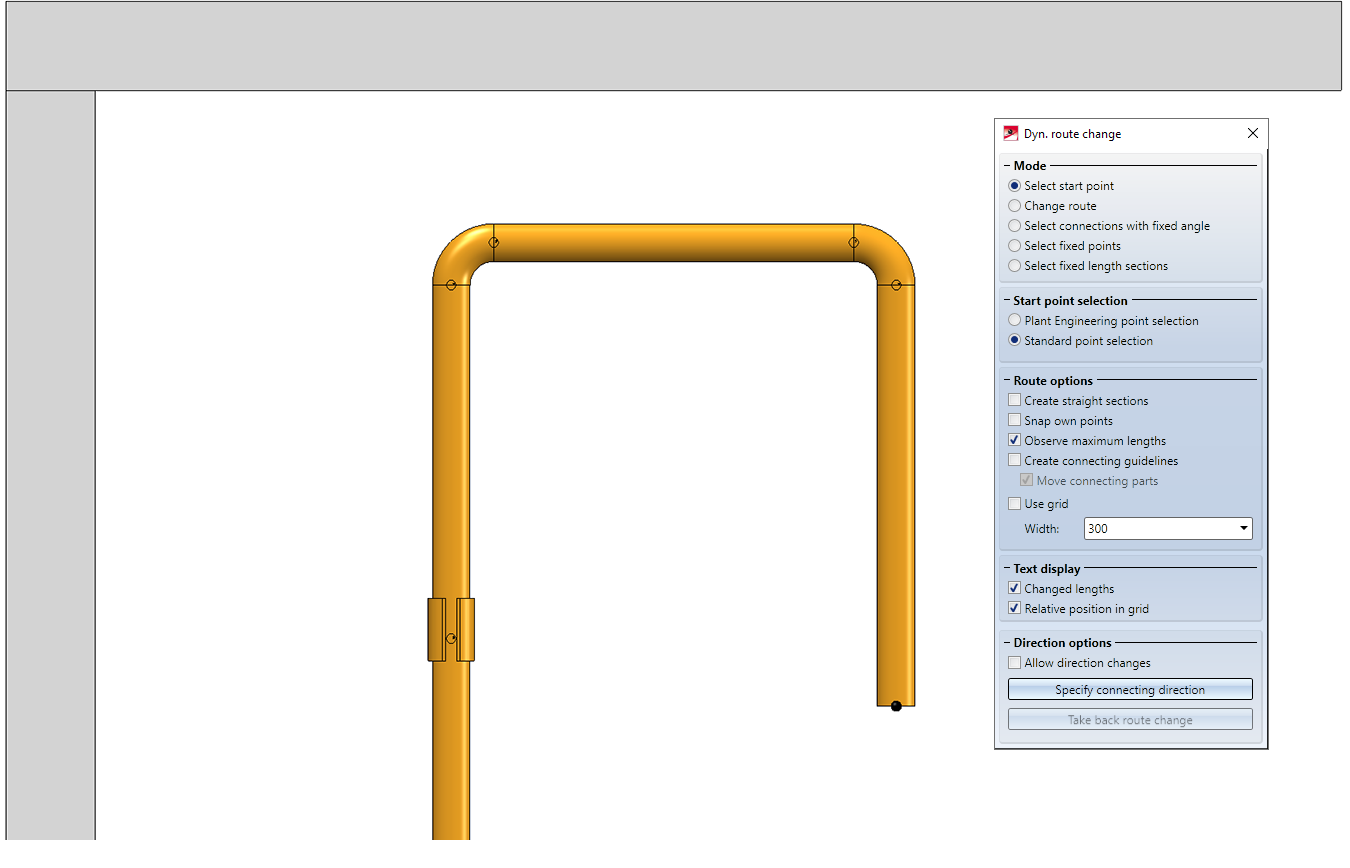
Example 3
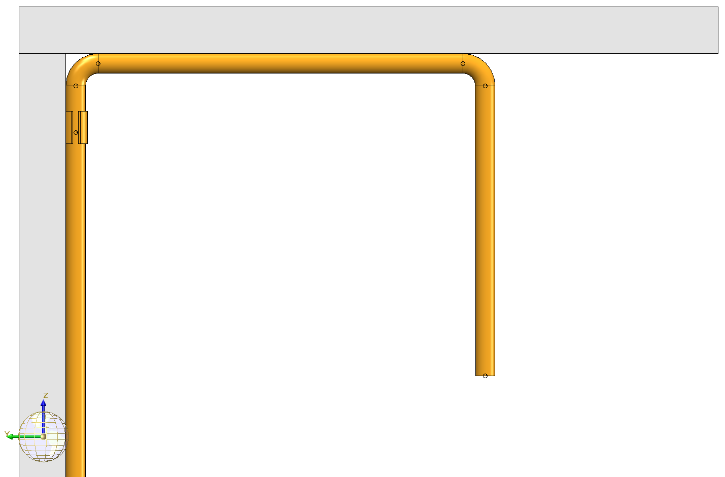
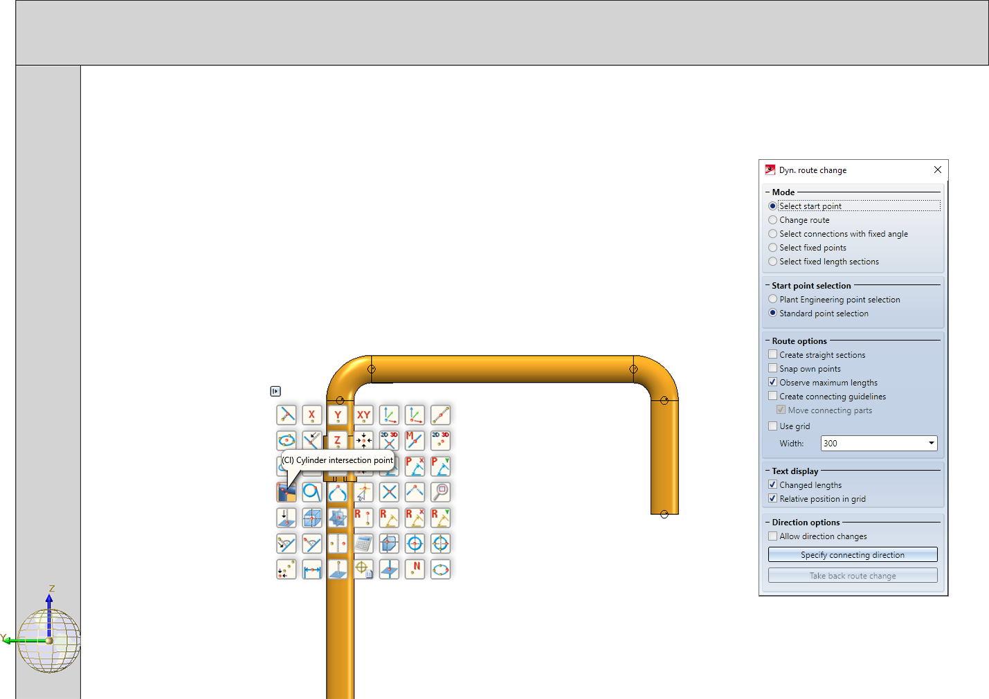
This example is similar to example 2, but here the pipeline route is changed so that the pipeline has a certain distance from the wall and the ceiling. The corner point of the pipeline is determined here as a cylindrical intersection. Then confirm the Plant Engineering connecting point with the middle mouse button.
.
Then we determine the target point with Relative (R) -Return (1), using the inner corner (2) as reference point. As distance we choose -200 in Y- and Z-direction.