- Delete individual part
- Delete several parts
- Example - Generation of replacement guidelines
- Delete all bolted flange connections in pipeline

Delete individual part
Plant Engineering > Part Tools > Delete part 
Use this function to delete individual parts. Identify the part you want to delete. If the part belongs to a pipeline, HiCAD will go up in the hierarchy of the selected part to the respective superordinate parts until the sub-part representing the complete part is found. In this way it is ensured that you delete the whole part. If the part belongs to no pipeline, HiCAD will go up in the hierarchy of the selected part to the respective superordinate parts until a part is reached that is not a "~Solid" or a "~Symbol" part.
When you use this function you distinguish between
- Part that have been placed on a guideline and
- Parts that have been placed in the model drawing without the help of a guideline.
Delete parts placed on guidelines
Liegt das gewählte Bauteil auf einem Leitkantenzug, dann wird der Abschnitt des Leitkantenzuges, der von dem gelöschten Bauteil abgedeckt wurde, automatisch restauriert. Das heißt, der Leitkantenzug wird in den Zustand gebracht, den er vor dem Einbau des Bauteils hatte.
Delete parts placed without pipelines
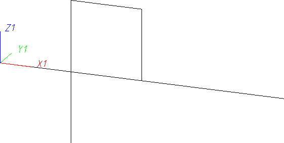
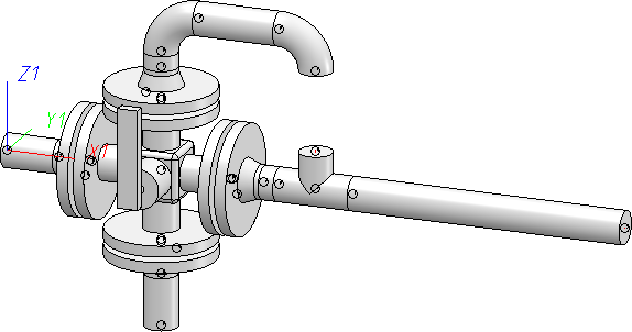
Sometimes it is easier to place parts directly instead of drawing a guideline that exactly matches the part to be placed, and then place the part onto it. To prevent a loss of data about the pipeline route when deleting these parts, "replacement guidelines" for parts that have been placed without guidelines will be created, as shown in the example with the elbow below.
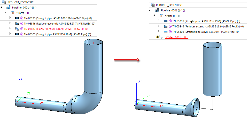
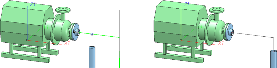
Please note that parts whose guidelines do not match their connection direction will be handled in a special way. In the example shown below this is the asymmetrical reducer. If you delete such a part, you have the option to adjust connecting points. In the model drawing the adjustment will be indicated by means of arrow symbols. The arrows show in which direction a connecting point will be moved for this purpose.
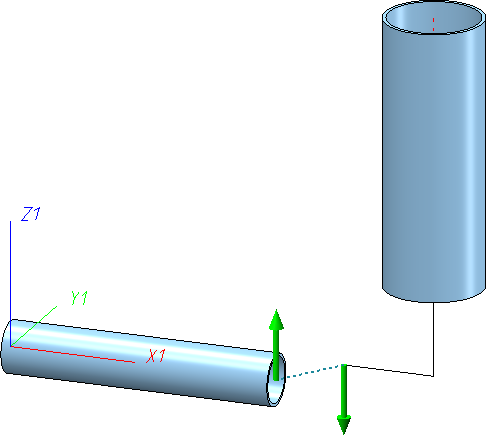
The arrows are selectable. As soon as you move the cursor over an arrow you receive an information about the expected result of a mouse click.
For instance, if you move the cursor over the left arrow in the drawing shown below, a line highlighted in a different colour (Special colour Marking 1) appears, showing you the route of the guideline. Also, an info text will be displayed, telling you that end points will be moved. In the example below, this text refers to the left end point of the horizontal pipe, which is also highlighted in the marking colour.
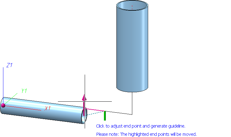
If this info text appears, you should check whether you actually agree with the displacement of the marked points. Please note that such points can also lie outside the border of visible areas.
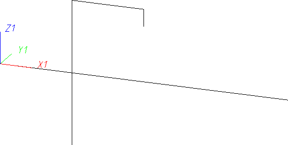
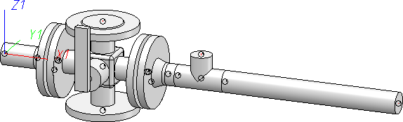
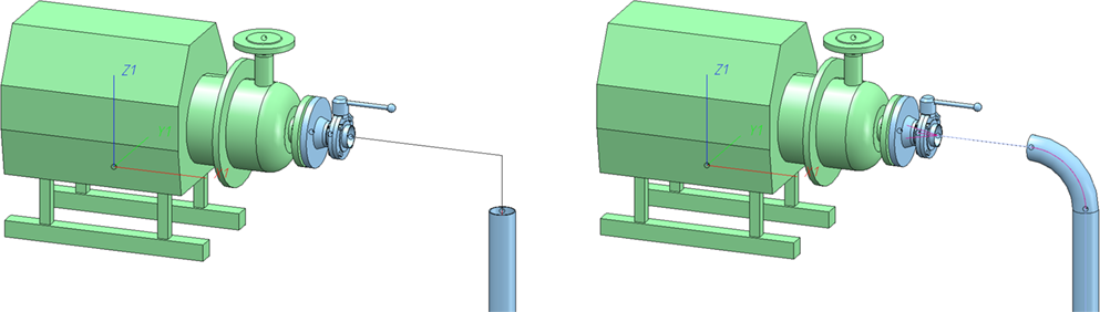
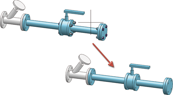
When you now click on the left arrow, the result will look as follows:
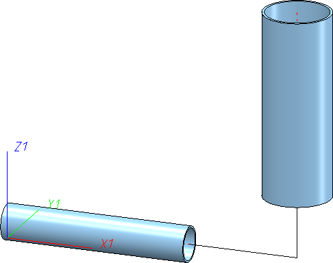
If you select the right arrow instead of the left arrow, the result will look as follows:
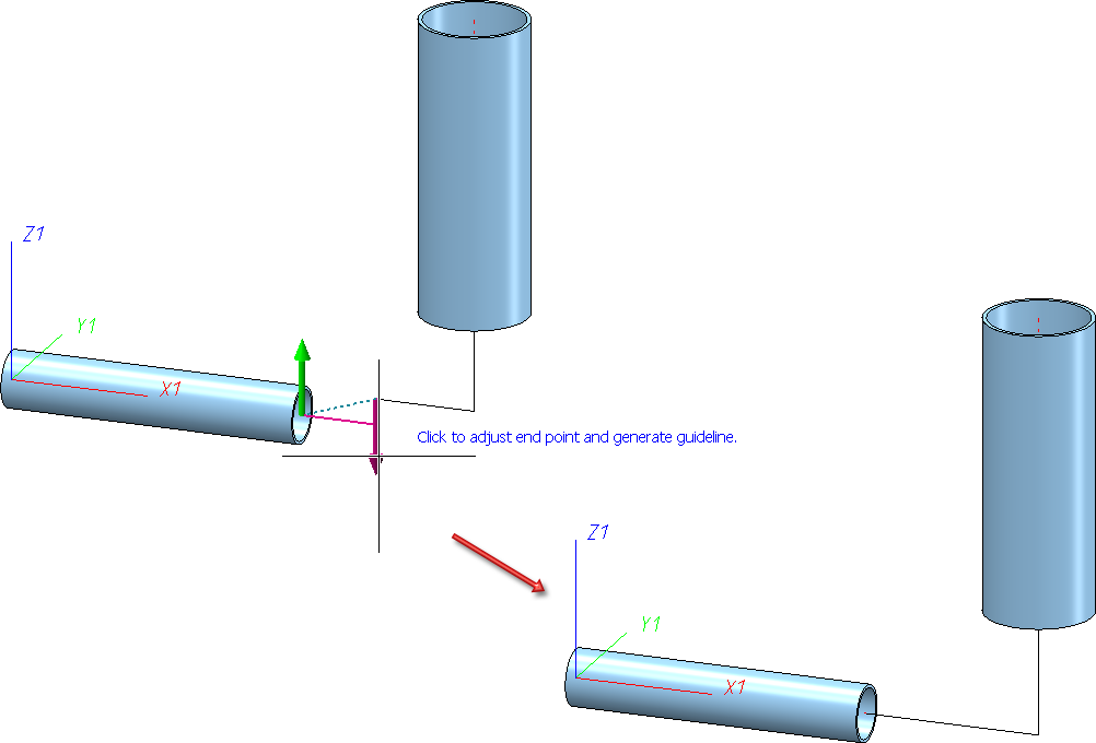
This time, no end point was moved; therefore, no info text appeared. instead, the vertical guideline section was lengthened a little bit.
In the background, a route change will be used for the adjustment of the end points. This means that HiCAD will always attempt to move the connecting point by length changes first. If this attempt fails, pipeline end points will also be changed and the info text appears.
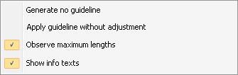
For parts that need to be handled in a special way - such as the asymmetrical reducer in the examples below - you can use additional functions in a context menu that you can open with a right-click:
|
Function |
|
|---|---|
|
Generate no guideline |
No guideline will be generated, the pipeline remains disconnected. (this can be preset in the Configuration Editor at Plant Engineering > Layout plan with the parameter Delete replaces parts with guidelines. |
|
Apply guideline without adjustment |
A guideline will be created along the dashed blue line. This will usually cause inflexions in the route. |
|
Observe maximum lengths |
A route change option that determines whether the maximum lengths of the pipes are to be observed when adjusting the connecting points by means of length changes. |
|
Show info texts |
Determines whether info texts are to be shown when you move the cursor over an arrow. |
- The function remains active until you end it by pressing the middle mouse button.
- The guideline creation can also be switched off if desired. To do this, open the Configuration Editor, go to Plant Engineering > Layout plan and deactivate the Delete replaces parts with guidelines checkbox. Please note however that if you delete parts that were not inserted on a guideline, the information on the pipeline routing will be lost due to the missing guideline.
- Parts that have been inserted as integral elements of an accessory set's product structure (e.g. seals) cannot be deleted with this function.
When deleting valves, counter-flanges in the same pipeline are also deleted.
Delete several parts
Plant Engineering > Part Tools > Del.  > Delete several
Use this function to delete several parts within a pipeline.
First, select a part that you want to delete and the properties of which may serve as a reference part for other parts to be deleted. When you select the part, the pipeline to which it belongs will also be activated.
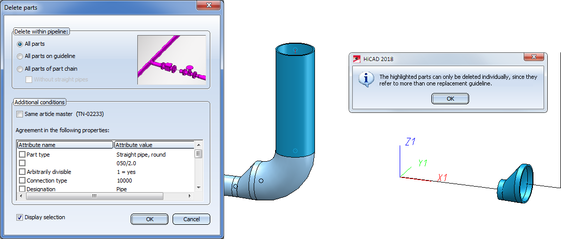
In the upper part of the dialogue window you define the area of the pipeline within which you want to delete parts.
- All parts within the complete pipeline.
- All parts on the guideline on which the reference part is located.
- All parts of the so-called "part chain" to which the reference part belongs. The "part chain" comprises all parts that can be reached starting from the reference part by going further to the next part via the connections, until an empty guideline or the end of the pipeline is reached. Instead of an empty guideline, a straight pipe can also delineate the end of a part chain.
In the lower part of the dialogue you can further restrict the selection of the parts to be deleted, by requiring specific properties of the reference part from the parts to be deleted, too - e.g. identical nominal diameters.
If the Display selection checkbox has been activated, the parts to be deleted will be highlighted and a confirmation prompt appears, asking you whether you really want to delete these parts.
When deleting several parts, one also distinguishes between parts that have been placed on a guideline and parts that have been placed directly, i.e. without the help of a guideline. If the part selection contains parts that require a special handling with regard to the Delete parts function, these parts will be excluded from deletion. In this case a corresponding info text will be displayed. For instance, this is the case if the direction of an automatically created guideline does not match the connection direction.
In case of parts for which more than one guideline would be possible, the generation depends on whether parts have been connected. The table below shows three models in which parts have been placed without guidelines, and the generated replacement guidelines after deletion of all parts.
|
|
|
|
|
|
|
|
|
When deleting parts, counter-flanges in the same pipeline are now also deleted. This particularly affects valves and flanges.
Example - Generation of replacement guidelines
This example will show you how useful replacement guidelines for deleted parts can be. Here, the guideline is used for the subsequent placing of a valve.
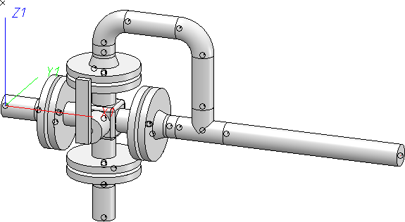
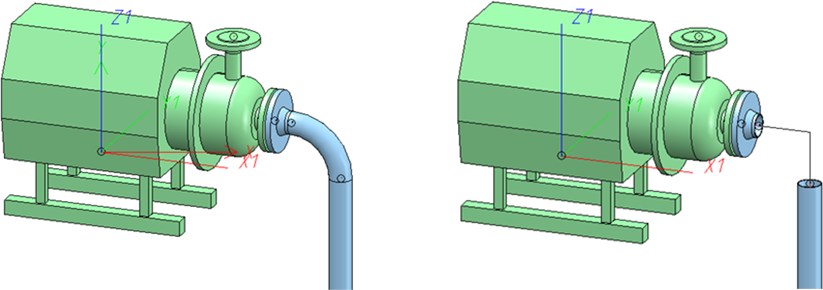
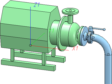
In the original drawing, a flange and an elbow have been directly mounted to a pump - without using a guideline. Now let us assume that you want to subsequently insert a valve between these two parts.
Step 1: Delete the elbow. This will automatically create a replacement guideline.
Step 2: Create some space with the Change route function.
Step 3: Place the valve, and place the deleted elbow again.
Step 4: Use the Close gaps function.
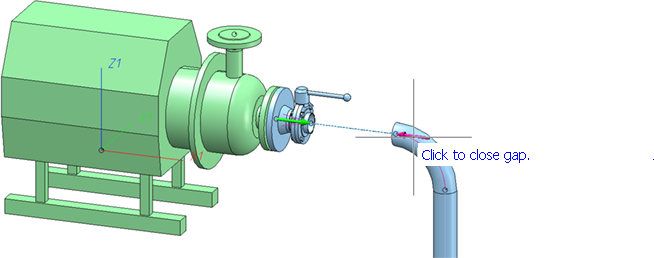
Finished!
Delete all bolted pipe connections in pipeline
Plant Engineering > Part Tools > Del. > Flange connection, bolted 
This function deletes all bolted flange connections that have been assigned to a part of the active pipeline.
Select a part of the pipeline with the cursor. Depending on the situation, HiCAD will ask you to activate a pipeline.
![]() Please note:
Please note:
You can also access this function via the context menu that you open by moving the cursor over an element of the bolting, e.g. a bolt, washer or nut, and then right-clicking this element.
