Discontinuation of “old“ HiCAD itemisation
As of HiCAD 2019 the “old” itemisation, i.e. the itemisation that was used up to HiCAD 2017, will only be available for model drawings that were already itemized with these functions. From HiCAD 2020 onwards, only the “new” itemization will be supported.
After calling the function, you need to confirm the Windows security prompt, asking you whether you want to allow changes to your system by the tool.
The TeamViewer will then automatically generate an ID and a Password, which may take some seconds.Let the support team member of the ISD Group have the ID and the Password to allow the remote access to your computer.
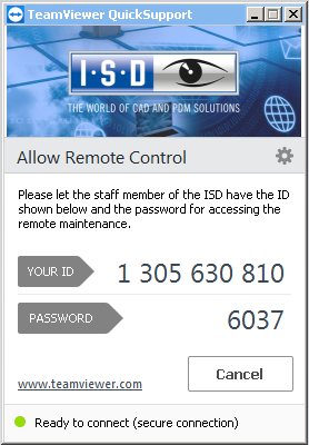
Further information on the TeamViewer can be found on the relevant website.
|
Important notes on using the Remote Maintenance tool and on protection of your data:
By contacting our Helpdesk via the Remote Maintenance you confirm that you have read and understood the above notes. |
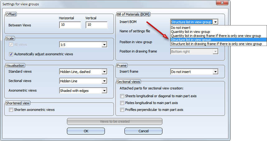
If you choose the output of structure assemblies in the Settings for view groups for drawing derivations, the assembly, i.e. Level 1 of the structure, will now also be output.
The docking windows for part variables has been enhanced.
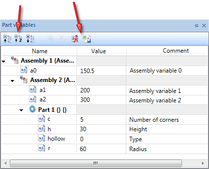
 icon to limit the display to the 1st and 2nd level of the part structure.
  symbol you can mark all unused variables for deletion. The deletion will only be carried out after clicking on Apply all changes
  .
.  to create a CSV file that contains a list of all variables.
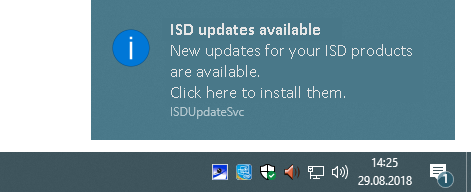
The ISD Update Service supports the automatic search for and installation of HiCAD updates (Hotfixes). For this you require the program ISDUpdateSvc.exe, that you can either activate during installation of HiCAD or install via the Windows Control Panel afterwards. Via this program you can activate the ISD Update Service. Further information can be found in the Automatic Installation chapter of the Installation Notes manual.
If the ISD Update Service is active, HiCAD checks upon its start whether a Hotfix is available. If this is the case, the following message appears at the bottom right of your screen:
Not only item numbers but also itemisation texts which consist of free text and attributes from different HiCAD/HELiOS sources. The new HiCAD part attribute Item index %PIDX can be used in order to create own incrementation in itemisation texts. If the itemisation text contains this attribute, each part with equal item number will be incremented on its own. This means that all n parts with common itemisation number will be numbered consecutively with an index from 1 to n. In practice, this is often used to allocate assemblies or parts with equal item number clearly to each information of the item number flag or BOM.
An example:
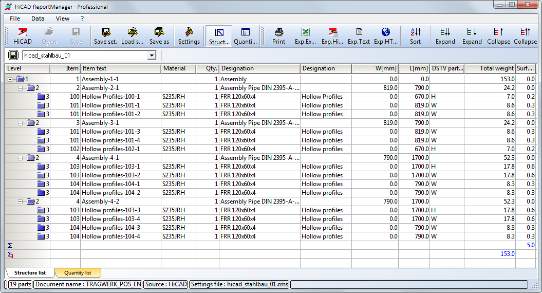
The depicted Steel Engineering drawing consists of three assemblies, which in turn consist of equal hollow profiles. The assemblies 1 and 2 are equal and consist of the parts 1b, 1c, 2b and 2c. Assembly 3 consists of four profiles, part of which are equal to 3a and 3c as well as 3b and 3d.
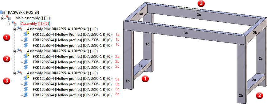
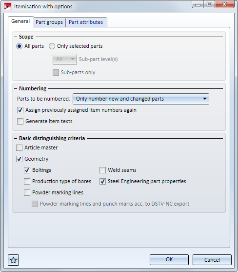
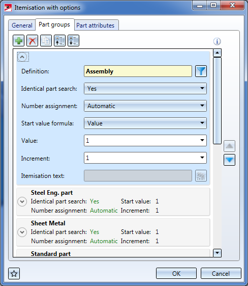
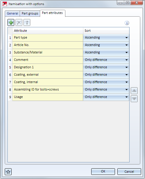
The drawing should be itemised. In order to set i.a. the new attribute Item index itemisation texts should be created automatically. For this, the function Drawing > Itemisation > Ite... > ... with Options will be used with the following settings:

Assemblies

Data source is the part itself.
Steel/Metal Engineering Parts
Data source is the part itself.
Result
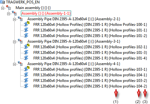
1=Part type, (2) Item number, (3) Item index
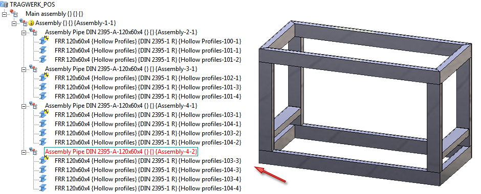
If a copy of assembly 3 would be inserted into the drawing and then itemised again, the item index continued with the next number (see example 3)
The itemisation text can also be issued via BOM.
 Please note:
When allocating the item index, it is not guaranteed whether already allocated indices still remain.
A simple example:
Let it be supposed that the original drawing contains three equal parts with position indices 1, 2 and 3. Now, the part with item index 2 will be deleted. The parts with index 1 and 3 remain. If the drawing is itemised automatically, two possible options can result:
As of HiCAD 2018, besides Quantity Lists also Structure Lists can be added in a Drawing Derivation. For this, the dialogue window Settings for view groups and the settings in the configuration management via Automatic drawing derivation > Production drawing > Usage-dependent > NAME > View group (here, the NAME is the name of the respective intended use) have been enhanced.
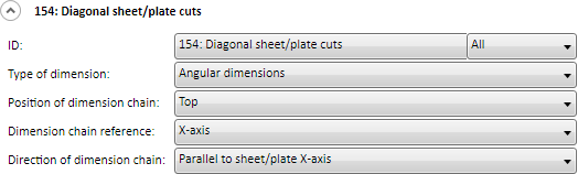
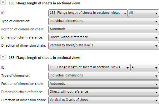
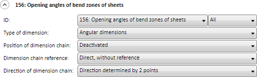
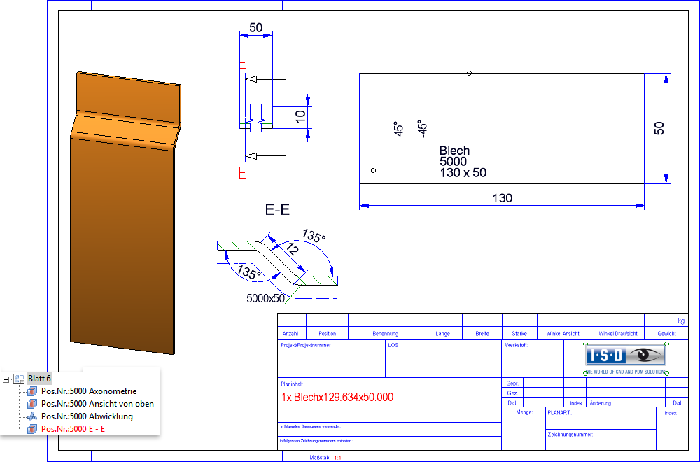
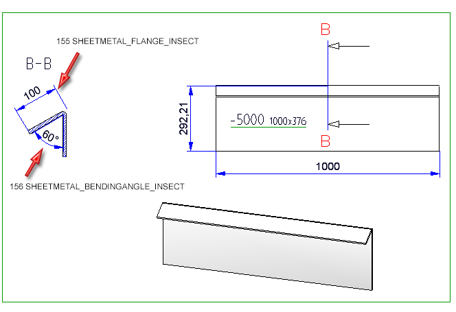
New dimensioning rules are available for sheet metal:
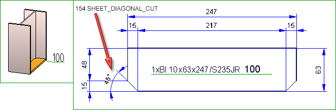
Rule 155 applies dimension to the flange length of sheets in sectional views, Rule 156 to the bend angle of sheets in sectional view. In case of flanges that are not parallel, the theoretical intersection point of the flanges will be dimensioned.
The recommended three settings for Rule 155 and 156 are simultaneously the new default settings for the sectional views of sheets in the workshop drawing (intended use: DEFAULT (SHEET METAL).
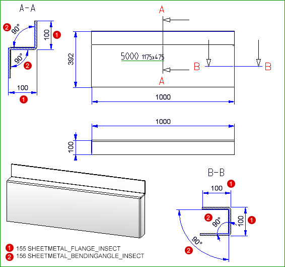
As of HiCAD 2018 SP2, the Section for generating sectional views always takes places at the shortest bend zone. The sectional views are created with depth limitation and perpendicular to each bend zone.
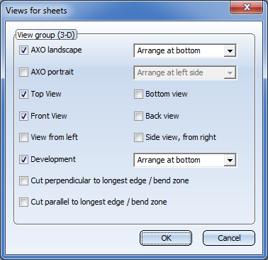
In addition, the dialogue window Settings for sectional views of sheets has changed:
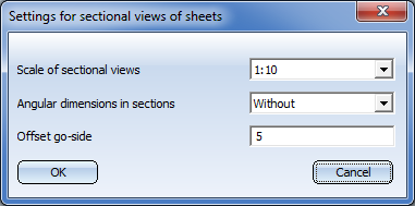
The following settings are possible:
The previous settings Angular dimensions in sections and Offset go-side are not available anymore. The representation of Angular dimensions can be defined via the new dimensioning rule 156 and the Offset go-side via the settings of the configuration management under Drawing > Representation > Sectional views with coating lines
As of SP2 it can be defined whether the dimensioning of 90° bend angle for sectional views of sheet metal can be defined in drawing derivation. The ISD default settings are that all bend angle are to be dimensioned.
In order to deactivate the dimensioning of 90° bend angle, currently the system files
must be adjusted manually.
STAB3DPAR.DAT
Here, the setting is done via
Display right angle for opening angle of bend zones of sheet metal? 1:yes, 0:no
0
STW_DIMSETTINGS.XML
Here, deactivating the dimensioning is done via line
</PARAM><PARAM Name="SHOWRIGHTANGLEOFBENDZONE" Typ="INT" Value="0">
If this line is not available it must be added manually.
Usage assignments can now not only be defined for assembly and part types provided by the ISD, but also for freely definable part types.
This means that you now have the option to define own part types you can, for instance, use own drawing derivation configurations for Steel Engineering series beams that are based on 2-D cross-sections. For example, you could define a part type called Series, and a corresponding usage assignment called Default(Series).
If you now create workshop drawings for model drawings with series beams and use the drawing parameters From configuration, the configuration Default(Series) will be used for all series beams with the part type Series.
Click here to view an example.
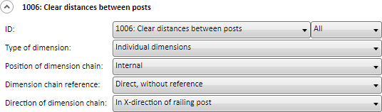
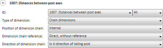
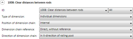
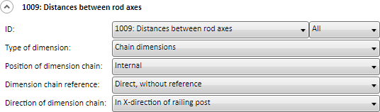
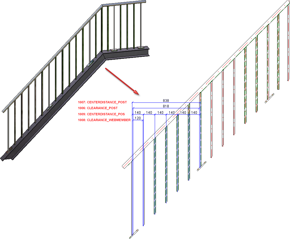
The automatic dimensioning for oblique railings has been improved. For this, dimensioning rules 1006 to 1009 for the stair railing segment have been changed:
In dimension type Chain of dimensions the post thickness will be taken into consideration, too. If the chain of dimensions of all fields is equal, only the chain of dimensions of the first field will be depicted.
In dimension type Chain of dimensions the post thickness will be taken into consideration, too. If the chain of dimensions of all fields is equal, only the chain of dimensions of the first field will be depicted.
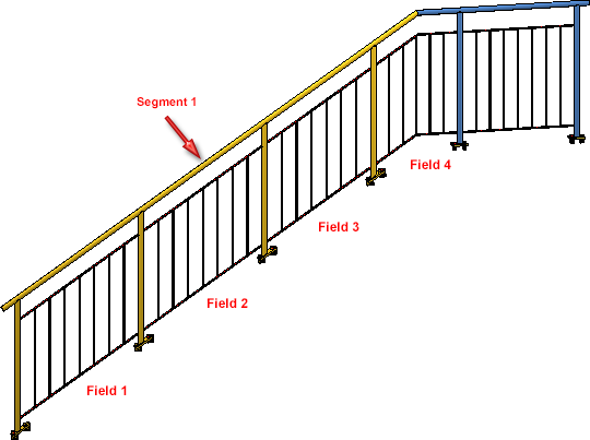
Example 1:
The depiction shows a staircase with equal distance between post and following vertical rod as well as between the vertical rods. The thickness of post and vertical rod are identical. The dimension and chain of dimensions of rules 1006-1009 are equal for each field.
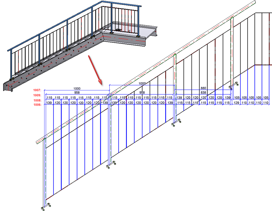
Example 2:
The oblique segment of the depicted staircase has individual distances for posts and vertical rods as well as different post and vertical rod thickness. Hence, dimension and chain of dimensions of rules 1006 to 1009 are not equal.
With regards to font size (e.g. for texts, measures, captions), HiCAD offers nominal size for fonts according to DIN EN ISO 3098-0.
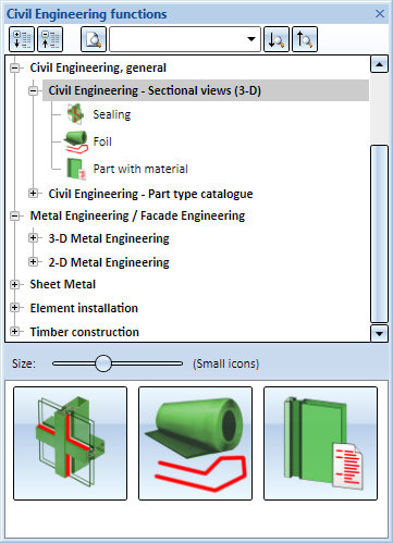
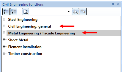
As of HiCAD 2018, the Metal Engineering functions Sealing, Foil and at Part with Material are also available in the following modules and suites:
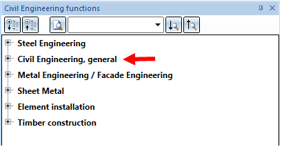
Previously, the functions have been part of the Metal Engineering-Ribbon and could be found via 3D-Section. As of HiCAD 2018, these functions are available via the docking window Civil Engineering functions under Civil Engineering, general > Civil Engineering - Sectional views (3D).
When saving SZA and KRA files, the polyhedron model will be reduced as far as possible. This applies to referenced parts and standard parts without processing in particular. By this, the file size and the time of saving and loading will be decreased. When testing this, the drawing shown below has been taken into account with approx. 1700 parts. About 900 parts of it were same parts - internally referenced. In HICAD 2018 SP1, the file size has been reduced from 33 MB to 11 MB.
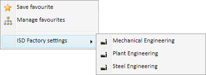
To several functions - for example Itemisation - settings predefined by ISD - ISD default settings and ISD factory defaults- are available in the scope of delivery of HiCAD. These are locked for editing and marked with  in Manage Favorites. In order to change and reuse these settings, they must be saved under a different name.
Itemisation - Context menu for favourites
With a lock symbol, marked favourites are locked by your system admin. They are also not deleteable or changeable. If you have questions, please contact your system admin.
In case of an update, the existing default settings can be prescribed by ISD and/or further settings may be added.
For Railings the following three new usage types are available in the Factory standards catalogue at Usage > Civil Engineering > Steel Engineering > Railing:
You can assign usage-dependent configurations for drawing derivations to these new railing elements.
The following configurations have been preset for the new usage types in the Configuration Editor at Automatic drawing derivation > Production drawing > Usage assignment:
|
Usage |
CONFIGKEY |
Utilized |
Consider for |
|---|---|---|---|
|
Post profile |
POSTPROFILE |
DEFAULT (STAHLROHRE) |
Yes |
|
Handrail profile |
RAILINGPROFILE |
DEFAULT (HOHLPROFIL) |
Yes |
|
Skirting board profile |
SKIRTINGPROFILE |
DEFAULT (FLACHSTAHL) |
Yes |
Furthermore, the default setting for the vertical rods used for infills has been changed:
|
Usage |
CONFIGKEY |
Utilized |
Consider for |
|---|---|---|---|
|
Rod |
WEBMEMBER |
DEFAULT |
Yes |
The default setting for Steel Engineering elements of the part type Round steel has also been changed:
|
Usage |
Part type |
Utilized |
Consider for |
|---|---|---|---|
|
All |
Round steel |
DEFAULT (STAHHLROHRE) |
Yes |
The parameters for sheet development have been enhanced. In the dialogue Sheet development parameters, the check box Processings is new.
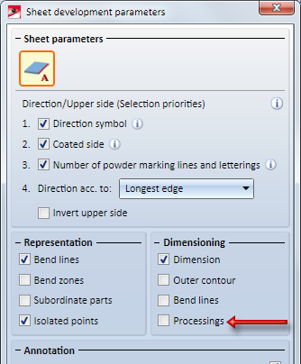
By ticking this checkbox you determine that bores and subtractions will be dimensioned on blank sheets.
If you tick the Processings checkbox below Dimensioning, dimensionings will also be created for bores and subtractions. The following must be considered: If the checkbox Separate chains of dimensions for bores and subtractions is activated from the tab Bores/Boltings of the function Drawing > Itemisation/Detailing > Dim... > Dimensioning Settings, separated chains of dimensions for bores and subtractions will be created.
Due to the discontinuation of HELiCON, the HELiCON-related attributes shown in the table below are no longer available after a new installation of HiCAD 2018 SP1. This change concerns the System attributes catalogue and the settings in the Configuration Editor at System Settings > Referencing > Synchronization of attributes.
|
Attributes for HELiCON |
|
|---|---|
|
%INSTANCE_ID |
HELiCON instance ID |
|
%ISCHANGED |
HELiCON IsChanged flag |
|
%ISSELECTED |
HELiCON IsSelected flag |
|
%LAST_INSTANCE_ID |
Last HELiCON instance ID |
|
$TN_COPY |
Copy of part name for HELiCON without HELiOS |
|
CONFIGURATIONID |
HELiCON configuration ID |
|
STATIC_PART |
HELiCON puchased part marking |
|
TRANS_INFO |
HELiCON transfer info |
After an update installation from an older version (before HiCAD 2018) the attributes will remain available.
A point option is available in 2D and 3D:  Intersection of tangents
With this option you determine the intersection of two tangents. HiCAD will request you to identify two graphical elements you require. The tangent will be defined by the end point of the graphical element lying closer to the cursor position. The new point is the intersection of both tangents.
In case if a graphical element is identified twice, for instance as arc, the intersection of tangents will be defined on both end points of the graphical element.
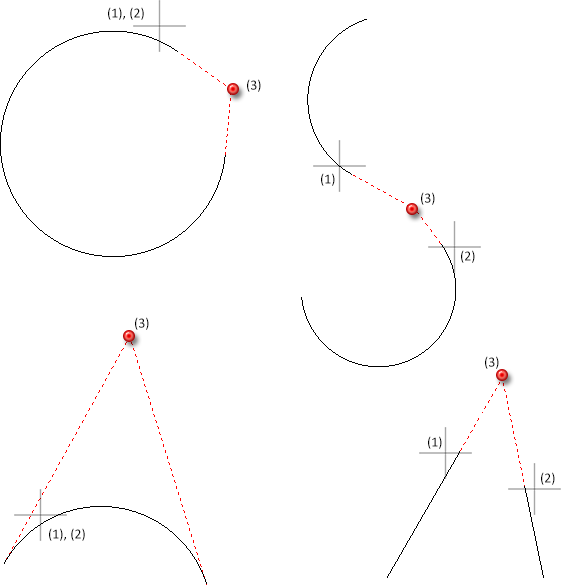
(1), (2) - selected graphical elements (here planar sketch), (3) identified point
HiCAD currently supports two different itemisation modes:
One property of each drawing is the question whether it is to be itemized in the old or remastered mode. In the Configuration Editor at System settings > Itemisation, revised > Itemisation mode you can specify the itemisation mode to be used in new drawings. For model drawings without a fixed itemisation mode, the Itemisation up to HiCAD 2017 mode will be used if they have at least been partly itemized.
In contrast to the Itemisation up to HiCAD 2017 mode, itemisation settings in the Standard itemisation as of HiCAD 2018 mode will not be saved globally, but by model drawings. For a management of individual configurations you can use the Manage favourites option that you already know from other functions. In the Configuration Editor at System settings > Itemisation > Default settings you can choose a Favourite defining the pre-settings for the Standard itemisation as of HiCAD 2018 mode. By default, settings for Mechanical Engineering, Steel Engineering and Plant Engineering have been pre-defined. Which of these Favourites will be used depends on the settings specified in the HiCAD Parameter configuration dialogue window.
The fixed part groups for the old Itemisation up to HiCAD 2017 are replaced by freely configurable part groups when you use the new Standard itemisation. You can use a part filter to specify the elements belonging to a part group.
Furthermore, two options for number assignment are available:
Advantages of the new itemisation:
|
|
The current settings of the itemization parameters are saved in the model drawing. Furthermore, the itemisation settings can be saved as Favourites, making individual settings for various industries available at the push of a button. |
|
|
The fixed part groups used for the old itemization up to 2017 are replaced with freely configurable part groups. You can individually specify via the part filter which parts are to belong to a part group. |
|
|
In addition to the item number, a freely configurable item text, e.g. for a detailed description of the type and quality of a service can be generated automatically. Item texts are composed of components of the type:
HiCAD part attributes can originate from the part itself as well as from the main part of an assembly, or a superordinate element with user-specific properties. Item text settings, too, can be managed as Favourites. |
|
|
The range of application for itemisation can be limited to selected parts and their sub-parts within a given number of levels. |
Other differences to the old Itemisation up to HiCAD 2017:
In previous versions the settings for texts and annotations could be set in the TXTPAR.DAT file. As of HiCAD 2018 this file is no longer available. Also, the corresponding setting options at  Settings > Basic settings > 2-D have been removed.
Instead, these settings are now available in the Configuration Editor, namely, at
The macros
are not available as of HiCAD 2018.
Dimensioning and annotations for beams, plates and sheets in workshop drawings can (if desired) be placed only on the visible outer side, i.e. bores/processings that are displayed with dashed lines in the HiddenLine dashed representation will not be dimensioned in the corresponding view.
To suppress the dimensioning for hidden bores/processings, the following requirements must be met:
</PARAM><PARAM Name="IGNOREHIDDENSUBPARTANDBORES" Typ="INT" Value="1">
The settings for the dimensioning only apply to dimensionings via dimensioning rules.
To suppress the annotations for hidden bores/processings, the following requirements must be met:
(1) Original beam; (2) Workshop drawing with suppressed dimensioning + annotation of hidden bores; (3) Without dimensioning + annotation of hidden bores
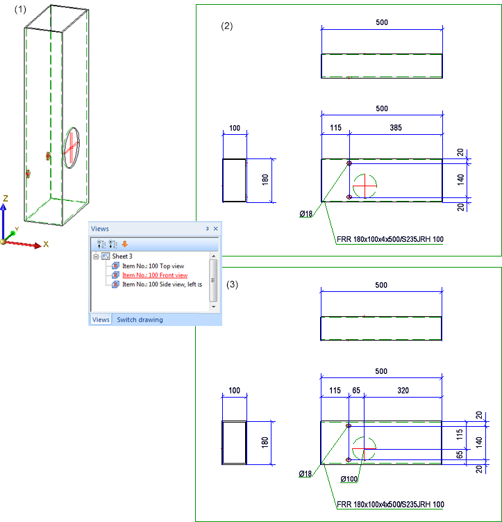
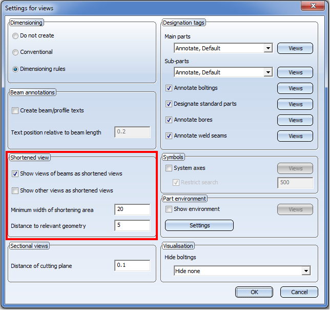
The parameters for the shortening of beams and other part types have been combined in the Settings for views dialogue window.
Please note:
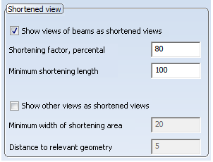
In HiCAD 2018 the Settings for views dialogue window for the Drawing derivation function has changed. If you load workshop drawings or model drawings with workshop drawings created with a version before HiCAD 2018 and then use the Change settings - Active view function, the Shortened view area of the previous version will be shown in the Settings for views dialogue window:
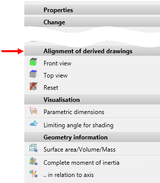
The definition of the front view and the top view for assemblies, general 3-D parts, beams, profiles, plates and sheets has been simplified.
For this purpose the functions in the context menu for parts (right-click part) at Properties >Alignment of derived drawings has been expanded accordingly. You have now the option to select an arbitrary plane for the definition of the front view or the top view. The same functions as the ones for the determining of processing planes are available to you.
If you work with the Management + BIM module you have the option to create the HELiOS attributes BENENNUNG (Designation) and SACHNUMMER (Article No.) of the detail drawing from templates. For this to happen, the parameter Create HELiOS attributes from FTD file in the Configuration Editor at PDM > Management + BIM > Production drawings must have been set to Yes (default). These templates can be customized with the Templates, Attribute assignment function.
To configure the HELiOS document attribute BENENNUNG (Designation for a multiple selection of beams to be output one only one drawing sheet, the file BIM_PDM_WSD_Multi_Designation.ftd file was available in previous versions. The default setting specified in this file has the following effect: If multiple parts/beams exist in the drawing, a (reasonably structured) list of the item numbers will be output, e.g. like this:
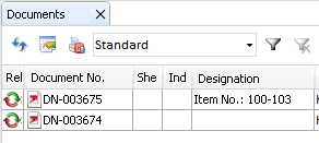
To make this configuration more flexible, the FTD file BIM_PDM_WSD_Multi_Itemnumber.ftd has been made available. If you want to output several part/beams on one drawing sheet, you can use a different attribute instead of the item number for the configuration of the document attribute BENENNUNG (Designation), e.g.
When selecting certain functions, a shaded polyhedron model preview will be attached to the cursor. For instance, this is the case when inserting or transforming parts, inserting new parts in the preview mode, or inserting standard parts.
This preview can be hidden temporarily by pressing and holding down the SHIFT key. This may be useful when working with complex models due to performance reasons. When the key is released, the preview is visible again.
This behaviour can also be inverted by a corresponding setting in the Configuration Editor at System settings > Visualisation > Temporary preview for part placement Possible setting options are:
The 3-D function Exploded view has been revised. Amongst other things, all displacements of the exploded view will now be documented. The corresponding log will be, similar to the Feature log, displayed in the new Exploded view docking window. You can also change exploded views via this docking window.
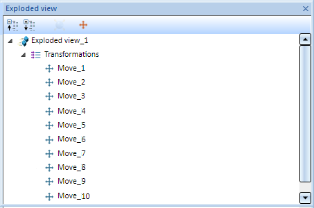
Exploded view docking window

HiCAD Basics - Overview of Topics
|
© Copyright 1994-2018, ISD Software und Systeme GmbH |