
Exploded view > Motion type > Move
If the Exploded view mode is active, you can use this function to define movements for the exploded view.
When you call the function, the Move dialogue window will be displayed:
![]()
Proceed as follows:
 and identify the desired part in the ICN or in the model drawing. The part will then be highlighted. If the Multiple selection checkbox is active, you can move several parts in one step. The selected parts will be listed in the window.
If you right-click on an entry in such a part selection list, you have the option to delete this entry if desired. Here, too, multiple selections are possible.
 Please note:
When you call the function, the active part or part list (=multiple selection) that was selected in the ICN or in the drawing will be shown in the part selection list of the dialogue window.
The displacement, i.e. the total value of the movement, can be determined selecting a point, by entering a value or by selecting two points. If required, choose the desired type of displacement before determining the direction. If the Select direction field is highlighted with an orange frame, you can determine the direction immediately. If this is not the case, click the  symbol to choose the direction. The direction can be determined by selecting an edge or a surface. In case of a surface, the direction will be defined by its surface normal. You can also use the functions of the context menu (right-click) to determine the direction.
The further procedure depends on the type of displacement you choose:
During rotation axis determination a preview of the movement will be shown.
Furthermore, you can right-click to open a context menu with the following additional functions:
|
|
Origin
|
|
|
X-axis
|
|
|
Y-axis
|
|
|
Z-axis
|
|
|
Step back
|
|
|
Cancel
|
Depending on the selected option a preview of the mounting tracks will be shown in the model drawing. To determine the appearance of the mounting tracks mounting tracks, use the parameters of the Default settings for mounting tracks  function, or, in the Configuration Editor, the settings at Drawing > Views > Exploded views.
If the Apply immediately checkbox has been activated, the transformation will be directly applied as shown in the preview, and entered into the Exploded view log, i.e. you do not have to click on the Apply button.
If the checkbox has been deactivated, use the buttons instead: Clicking OK applies the displacements and closes the dialogue window. Clicking Apply also applies the transformation, but the dialogue window remains open, enabling you to define further transformations if desired. Clicking Cancel closes the dialogue window, and transformations that have not been applied yet will be discarded.
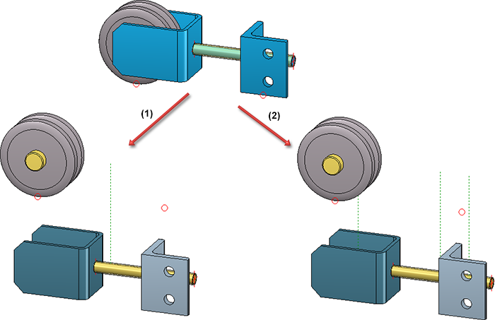
In the image below an exploded view has been created for for the three marked parts by means of displacements: (1) One mounting track for all parts; (2) Mounting track for each part
Each applied transformation will be recorded in the Exploded view docking window, e.g.:
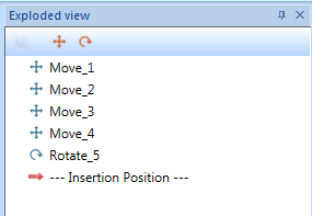
Via this "explosion log" you can also change transformations of the exploded view subsequently.
![]() Please note:
Please note:
This function can also be called via the theExploded view docking window.


Exploded View • Representation Functions
|
© Copyright 1994-2018, ISD Software und Systeme GmbH |


