Plant Engineering - What's New?

Service Pack 2 2024 (V 2902)
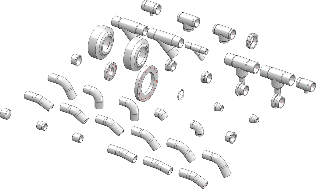
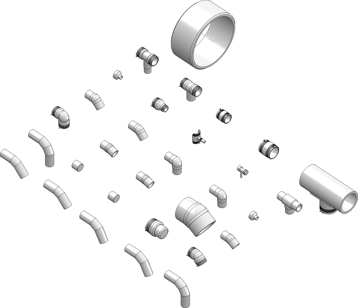
SIKLA clamps
The range of available parts has been expanded in SP2 to include additional variants for pipe clamps from SIKLA.
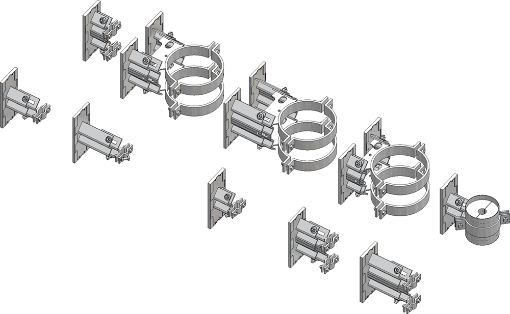
The variants can be found in the list file sikla_pipe_supports.lst. It contains the following variants:
|
File |
Designation |
Type |
|---|---|---|
|
LA-HV-150.VAA |
Loose bearing LA-HV-150 |
Pipe clamp |
|
LA-HV-200.VAA |
Loose bearing LA-HV-200 |
Pipe clamp |
|
LA-HV-90.VAA |
Loose bearing LA-HV-90 |
Pipe clamp |
|
LC-HV-150.VAA |
Loose bearing LC-HV-150 |
Pipe clamp |
|
LC-HV-200.VAA |
Loose bearing LC-HV-150 |
Pipe clamp |
|
LC-HV-90.VAA |
Loose bearing LC-HV-90 |
Pipe clamp |
|
LD-HV-150.VAA |
Loose bearing LD-HV-150 |
Pipe clamp |
|
LD-HV-200.VAA |
Loose bearing LD-HV-200 |
Pipe clamp |
|
LD-HV-90.VAA |
Loose bearing LD-HV-90 |
Pipe clamp |
|
LK-HV-150.VAA |
Loose bearing LK-HV-150 |
Pipe clamp |
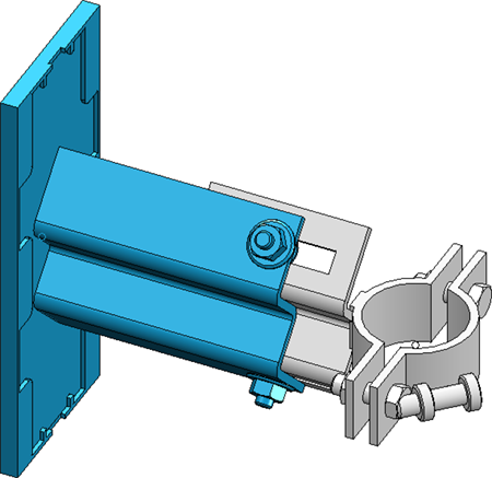
The fastenings of the clamps are modelled as sub-parts so that you have the option of subsequently adjusting their position.
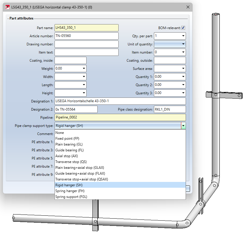
Support type and support type symbols for pipe clamps
The Pipe clamp support type attribute - attribute name PIPE_SUPPORT_TYPE - can be assigned to pipe clamps using the Part attributes function. By assigning this attribute, different pipe support types can be displayed in ROHR2.
Three additional support types are available in the Part attributes mask as of SP2:
- Rigid hanger,
- Spring hanger and
- Spring support.
In addition, the entries now also show the ROHR2 abbreviations so that you can assign them more easily.
Furthermore, from SP2 it is possible to define support type-dependent symbols to be used for visualisation in an isometric drawing.
If a support type has been assigned to a pipe clamp and a symbol has been assigned to this support type, the original symbolic representation of the pipe clampin the isometric drawing is replaced by the symbol of the support type.
The symbols for the support types can be found in the PlantParts\Symbols\PipeSupport sub-folder.
In the same directory you will find the file support_type_symbols.txt, which makes the assignment between the support types and the symbols. The file uses the abbreviations known from ROHR2 for the support types. A symbol is assigned using a line of the form
Abbreviation="filename without extension"
Example:
FP="fixed_point"
This means that the symbol fixed_point.FGA is assigned to the support type FP.
DBPlantDataImport - Attribute initialisation
The DbPlantDataImport.exe program is the central tool for updating the HELiOS database to the content required for the current version of HiCAD in the Plant Engineering module. DBPlantDataImport can be used to preset attribute values for articles and documents. These initializations are used when synchronising the part data with HELiOS in order to assign the attributes of newly created articles and documents.
As of SP2, the attribute values are initialized as shown below.
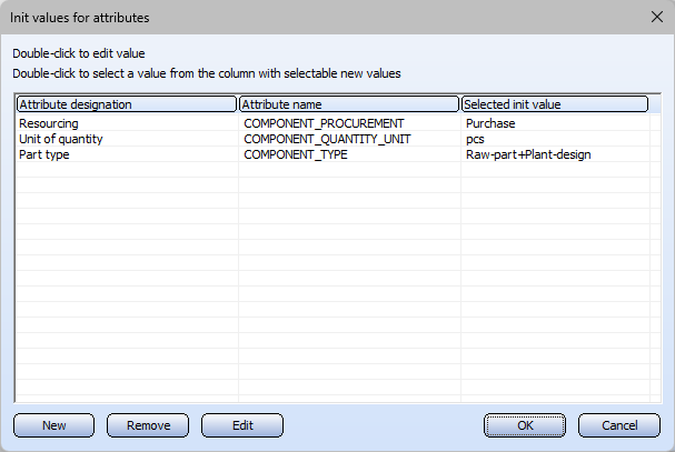
Initialization, Article - defaults
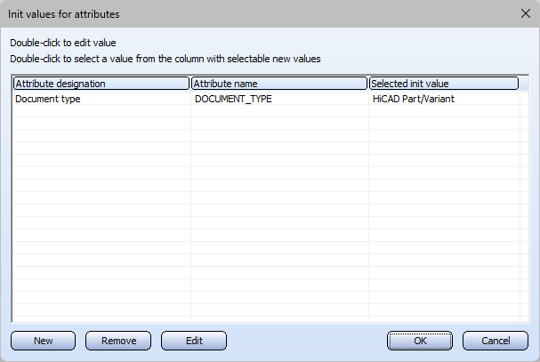
Iinitialization, Document - defaults
The initializations are saved in the DbPlantDataImportConfig.xml file in the HiCAD sys directory. The version of this file included in the scope of delivery from SP2 contains the attribute AddDefaults with the default value 1
<AddDefaults>1</AddDefault>
This setting ensures that the above-mentioned default initializations are inserted. Each time the configuration is saved, AddDefaults=0 is set so that once saved, the default settings are no longer changed automatically. By setting AddDefaults=1 again, the default initializations can be added again, e.g. after deleting the ISD initialization.
Isometry and pipe spool drawing
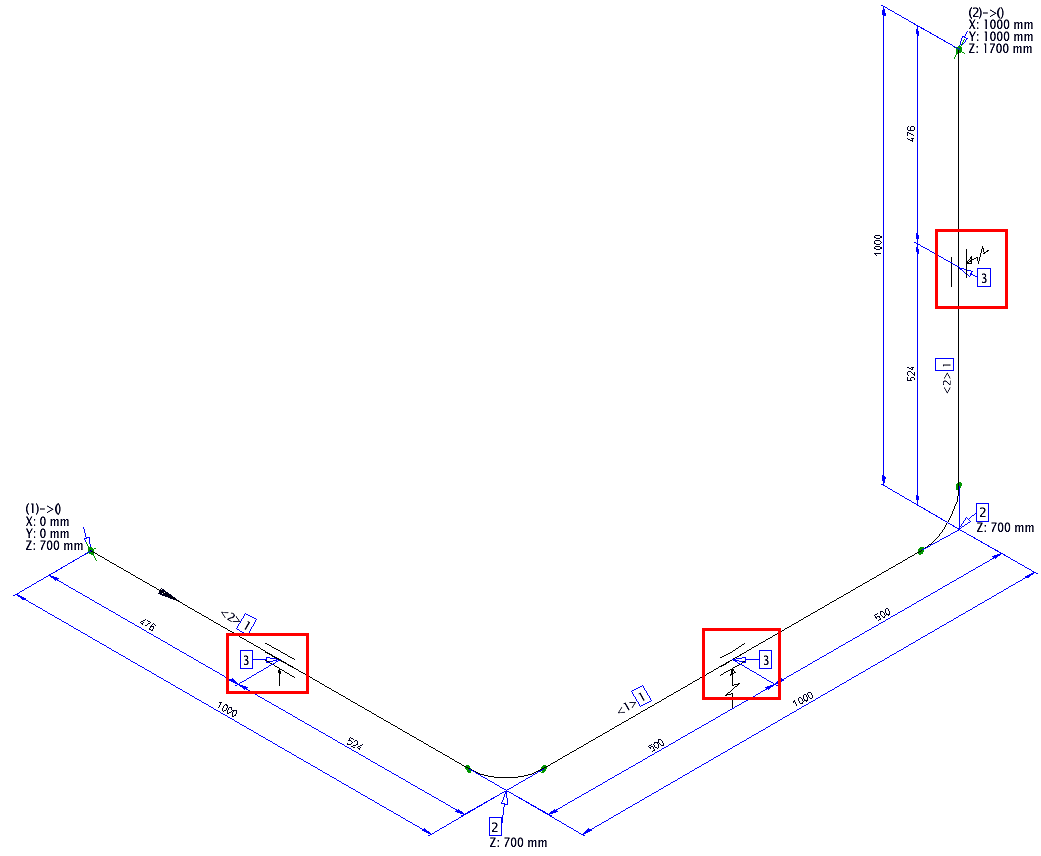
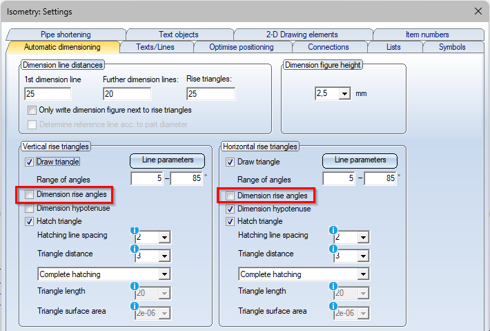
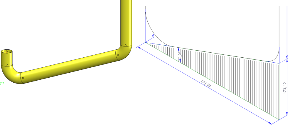
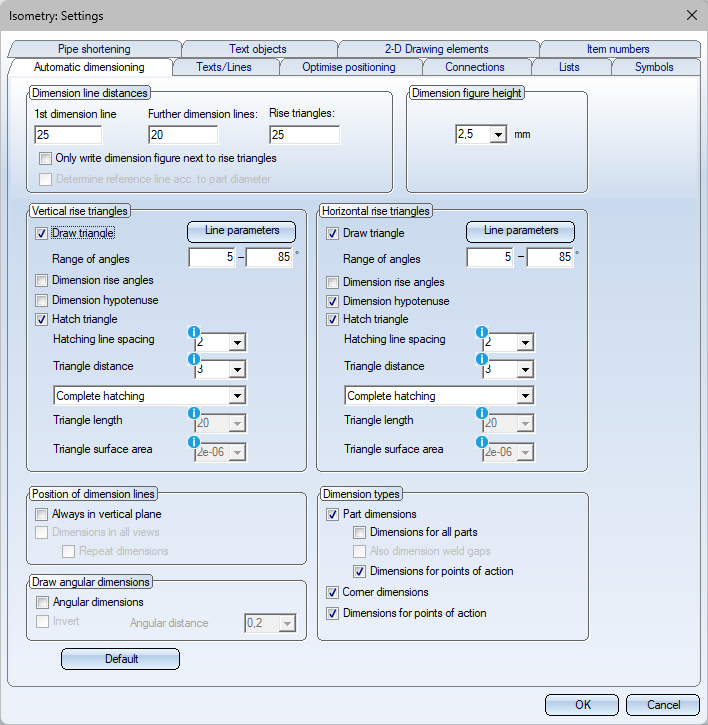
Angles in the rise triangles
As of SP2, the rise angles can be drawn into the rise triangles of an isometry. For this purpose, the Automatic dimensioning tab in the isometric settings has been expanded to include the Dimension rise angles checkbox for horizontal and vertical rise triangles.
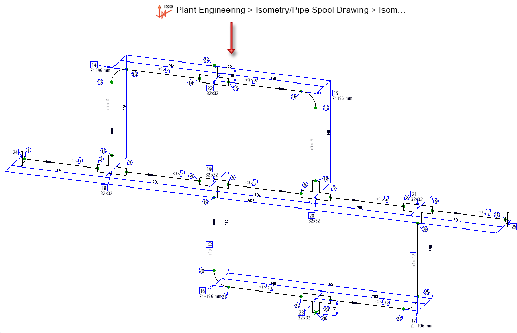
The following image shows a vertical rise triangle with angle dimension.
Recolour pipe part symbols
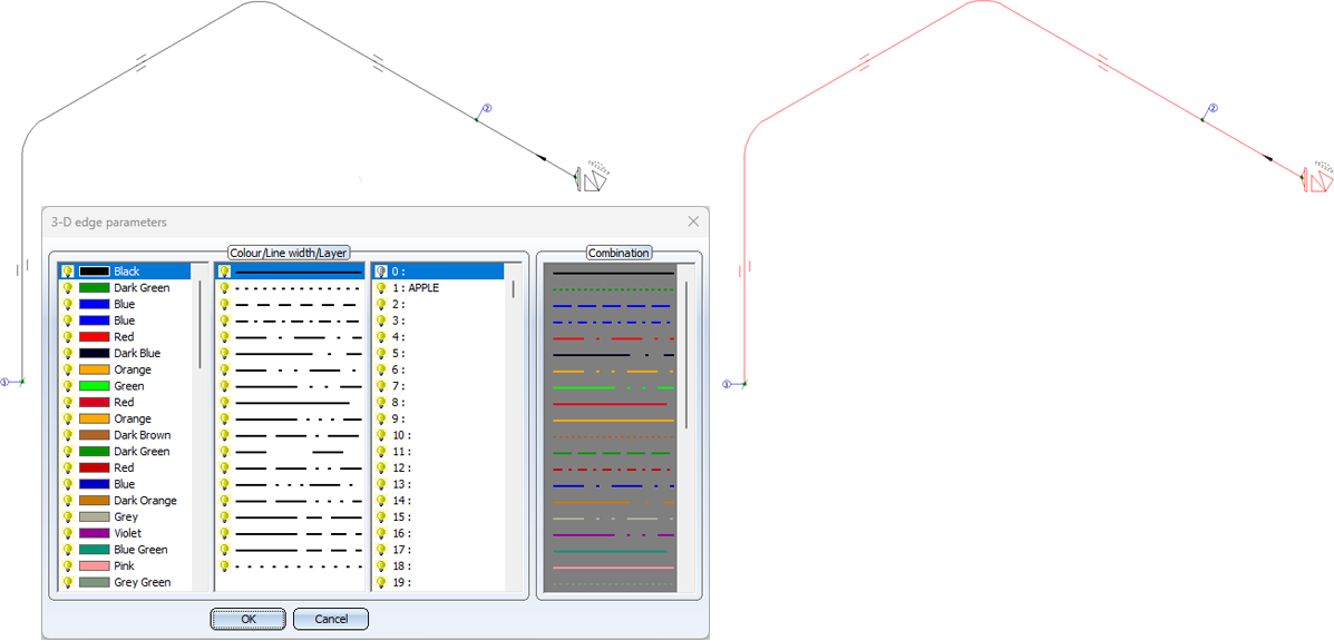
The colour of the symbolic representation in the isometry is defined when a pipe part is inserted. The corresponding Plant Engineering Settings on the Part insertion tab are taken into account in the process.
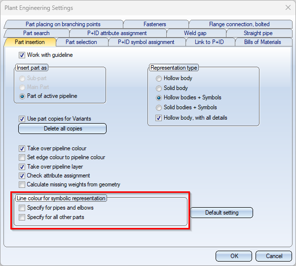
Sometimes, however, it only becomes apparent later that the colour or line type of the symbolic representations should be changed. Particularly when printing, there is often a desire to differentiate the pipework from other drawing elements - such as dimensions - in the visualisation. Previously, the colour of the symbols had to be laboriously adjusted by hand. As of SP2, this is now possible in a single step with the Recolour pipe part symbols  function. To do this, the 3-D edge parameters window is opened after calling up the function. Immediately after selecting the desired parameters, they change colour in the isometry.
![]() Please note:
Please note:
- In particular, symbols such as weld seams, flow symbols or even indicated parts are not recoloured. Dimensionings and rise triangles also retain their colour.
- The function is a post-processing step. This means that the colour is only changed for the current isometry. In particular, the colour is reset to the original colour when the isometry is regenerated.
- As only one crosshairs and one north arrow are generated, you may need to move both figures on the sheet using the 2-D part > Transform > Move
 > Move part, free (2-D) function.
Create pipe spool drawing from pipe spool drawing
The Pipe spool drawing context menu, which you activate by right-clicking on a pipe in the pipe spool drawing, has been expanded to include the From new part selection function. Previously, this option was only available in the Multiple selection context menu.
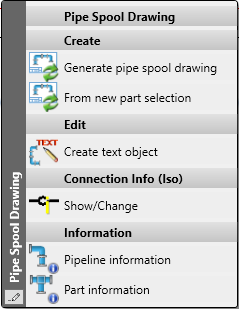
It is now possible, for example, to create pipe spool drawings for individual pipes or pipe sections directly from an overall pipe spool drawing.
Service Pack 1 2024 (V 2901)
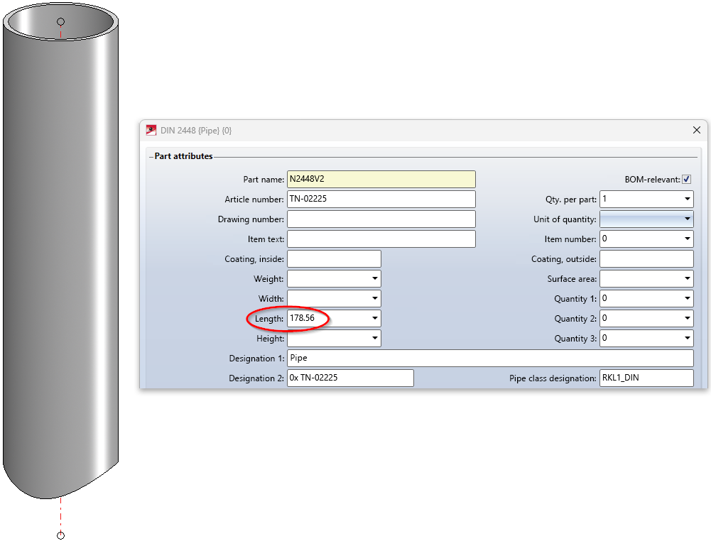
Length of inserted pipes
Previously, the length of inserted pipes was always calculated up to the center of the pipe into which it was inserted. As of SP1, the length is now calculated correctly. This also applies to the isometry and the pipe spool drawing.
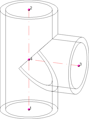
Knee - Horizontal bending direction (VEERING_RESTRICTION)
The new HELiOS attribute VEERING_RESTRICTION complements the already existing attributes BENDING_RESTRICTION (bending direction) and PLANE_RESTRICTION (bending plane) in that also with VEERING_RESTRICTION the route of a guideline can influence the part search.
To make this attribute available in your HELiOS database as well, you may have to update HELiOS for Plant Engineering before. To do this, use the DbPlantDataImport.exe tool.
The VEERING_RESTRICTION attribute knows the following values:
|
0 |
no restriction, treated like regular knee; in this case, however, the attribute should simply be left unassigned, which has the same meaning. Not used in search conditions. |
|
1 |
only allowed to the right |
|
2 |
only allowed to the left |
|
3 |
symmetrical; allowed to the left or right |
The only part type whose insertion is affected by the attribute is the Knee.
Example - VEERING_RESTRICTION
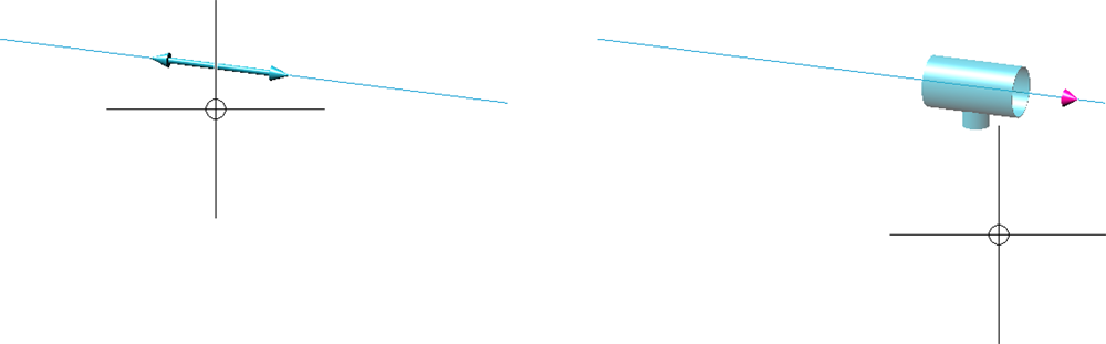
In the following example, a simple composite edge has been automatically assigned two knees. The flow direction is from left to right.
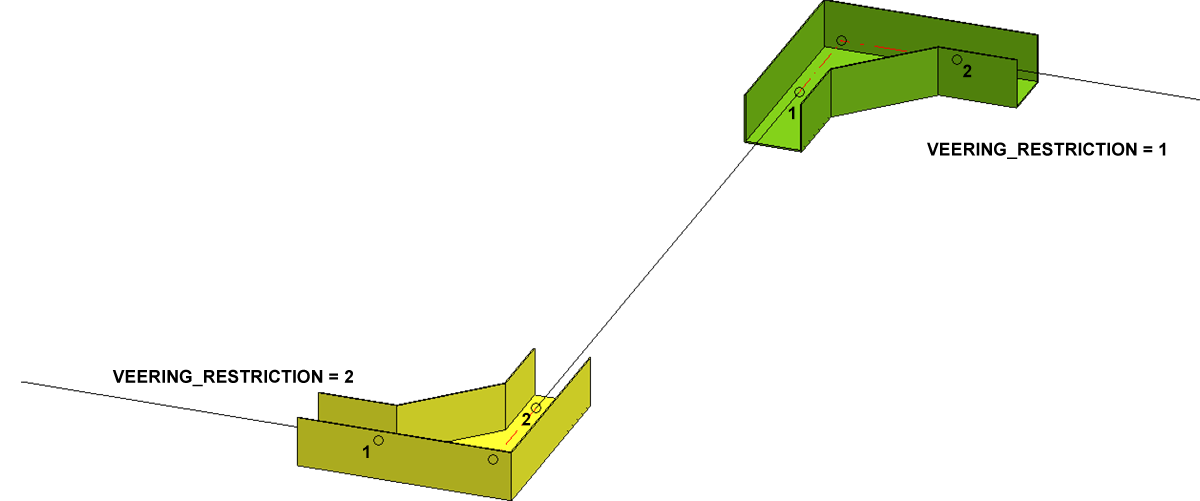
When searching for a suitable knee for bends to the left, HiCAD adds the following condition to the HELiOS search:
VEERING_RESTRICTION = ''\'3*'\'2*''
This means that only parts that do not have VEERING_RESTRICTION, are symmetrical or bend to the left will be found.
In the above example, the yellow knee was found and fitted.
When searching for a suitable knee for bends to the right, the following condition was added to the HELiOS search:
VEERING_RESTRICTION = ''\'3*'\'1*''
This means that only parts that do not have VEERING_RESTRICTION, are symmetric or bend to the right will be found.
In the above example, the green knee was found and installed.
For symmetrical parts, one would like to be able to additionally express that these can be used for both left and right bends, which at the same time implies that these parts may also be installed against the flow direction (namely for left bends).
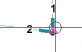
In the following example, the same composite edge has been fitted with a part whose VEERING_RESTRICTION has the value 3:
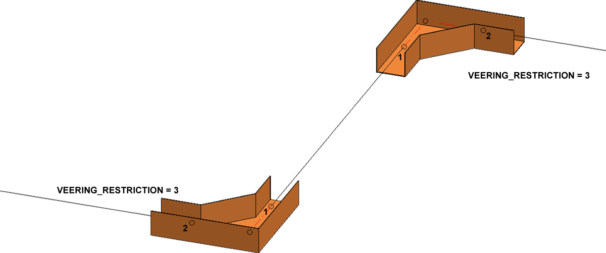
Note that for the bend to the left the order of the connection points is switched , so the part was installed against the flow direction running from left to right.
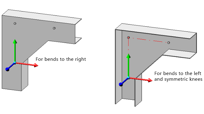
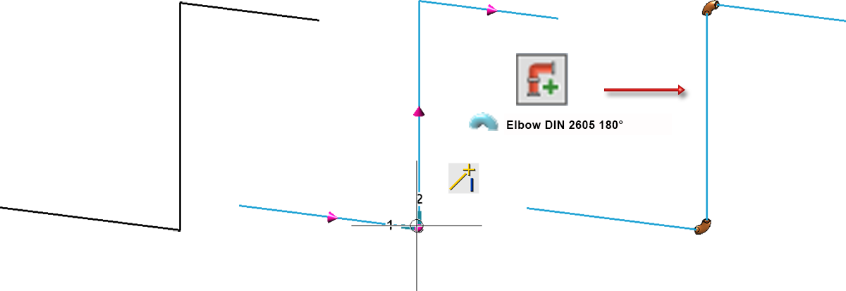
To use a custom variant with VEERING_RESTRICTION, this attribute must be assigned in the VAA file. The knees follow the usual design guidelines for knees. For the above examples, the variants look as follows:
Presettings for article attributes in the Configuration Editor
The MATERIAL, SURFACE AREA, WEIGHT and VOLUME attributes were previously considered fixed by pipeline planning, although they have been separately definable in the Configuration Editor for some time. As of Service Pack 1, these specifications are now taken into account.
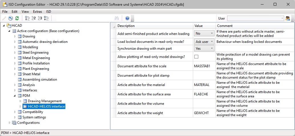
However, a special feature applies to variants, which must of course work for all settings in the Configuration Editor. Therefore, material, surface area, weight and volume will still be assigned to the MATERIAL, SURFACE AREA, WEIGHT and VOLUME attributes in variants. During part data synchronization, however, these four attributes are then mapped to the attributes defined in the Configuration Editor.
Automatic checking of nominal diameters, pipe lengths and part structure
In addition to checking nominal diameters, pipe lengths and pipeline structure with the functions at Plant Engineering > Pipeline Tools > Coll... HiCAD also offers the possibility to perform these checks automatically when loading and saving layout plans or when switching from a P+ID to the layout plan. Previously, this could be defined in the Plant Engineering settings under Actions during Load/Save. As of SP1, this tab is no longer available. Instead, the parameter Checks the entire drawing is available in the Configuration Editor at Plant Engineering > Plant Engineering drawing check.
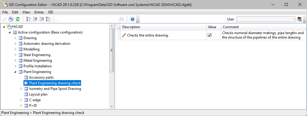
If this checkbox is active, HiCAD automatically performs the following checks during load/save:
- Nominal diameter matings
Here it is checked whether only parts with matching nominal diameters are connected with each other in the layout plan.
- Pipe lengths
It is checked whether inadmissible pipe length changes have been made in the layout plan. - Structure of the pipelines
The part structure of all pipelines is checked here.
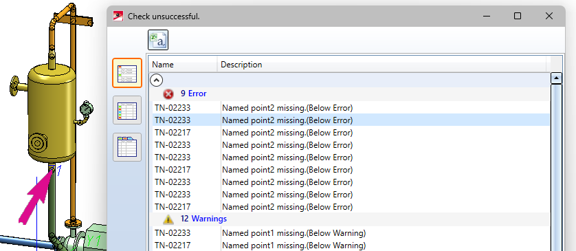
If errors occur during the check, they are displayed in a results list, e.g.
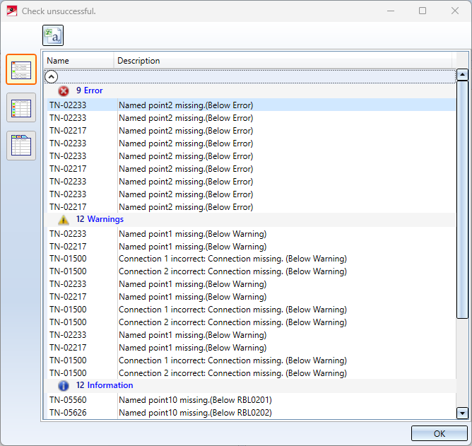
If you click on one of the errors in the list, the corresponding location in the layout plan is marked accordingly.
Changes/enhancements for pipe part insertion
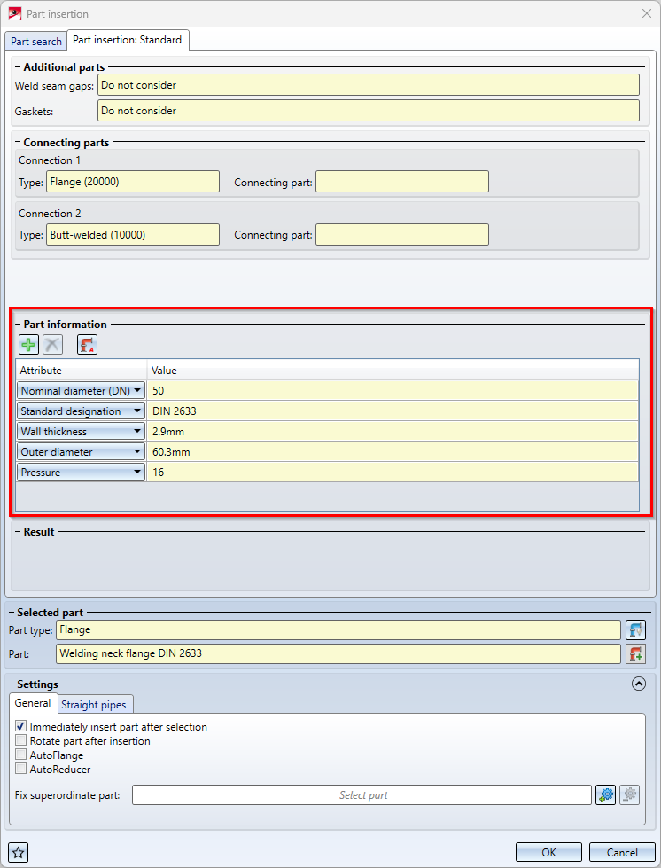
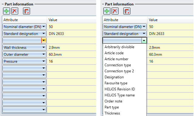
Additional part information
The tab that is displayed with the Pipe parts function after selecting a part has been extended. Additional information about the selected part is now displayed here, e.g.
|
|
Clicking this button inserts a new row in the attribute list after the current line. Using the selection box of the row, you can then select the attribute to be displayed.
To change the attribute display of a row, simply select the desired attribute in the selection box. |
|
|
A click on this button deletes the current row of the attribute list.. |
|
|
Clicking this button restores the default state of the attribute list.. |


Undo/Redo
As of Service Pack 1, the Undo and Redo functions of the transparent toolbar or the quick access toolbar can be used within the Pipe parts function after a part has been inserted.
Free point selection
The context menu for defining the insertion position has been extended.
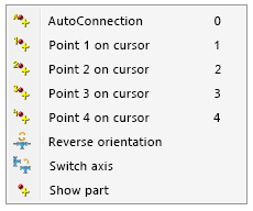
The Show part option for freely positioning the part at an individual point has been added. For this purpose, a preview of the part is displayed where you can select any point.
After selecting the point, the part is attached to the cursor at the corresponding position and can be freely positioned in space.
Another option is to select any point and then select an edge for positioning. Then the cursor is attached to the selected point of the part. This is projected onto the edge, so you can align the part to the selected point on the edge.
Revised "Set all" option
In the Part insertion dialogue window, the checkbox In all similar places has been removed. Instead, two new options are now available in the Selected part area.
|
|
Insert everywhere This option allows you to automatically insert a part in all similar places. If you have not selected a part so far, first define the insertion position of the selected part type, e.g.
Then select the desired part after clicking on Example
|
|
|
Highlight similar places This symbol is only active if you have already selected a part. All possible insertion positions are then displayed for this part, so that you can explicitly trigger the insertion at the desired positions with one click.
A special feature is the insertion of flanges in all places. If no position is individually pre-marked, counterflanges are matched only with identical flanges. However, flanging can also be performed at free ends by preselecting a free end. |


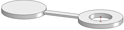
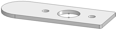
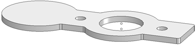
Line blanks acc. to DIN2626
The parts inventory has been expanded to include line blanks acc. to DIN 2626. The new parts are divided into six groups:
|
|
|
|---|---|
|
DIN2626 TYP A
|
Blind Disk Variant files:
You can find these variants summarized in the list file DIN2626-TYP_A-BD.lst. |
|
|
|
|
DIN2626 TYP A
|
Perforated Disk Variant files:
You can find these variants summarized in the list fileDIN2626-TYP_B-PD.lst. |
|
|
|
|
DIN2626 TYP C
|
Orifice Plate
You can find these variants summarized in the list fileDIN2626-TYP_C-OP.lst. |
|
|
|
|
DIN2626 TYP D
|
Spectacle Blind As A Figure-8 Blank Variant files: DIN2626-TYP_D-SB8B-PN10.VAA DIN2626-TYP_D-SB8B-PN100.VAA DIN2626-TYP_D-SB8B-PN16.VAA DIN2626-TYP_D-SB8B-PN160.VAA DIN2626-TYP_D-SB8B-PN25.VAA DIN2626-TYP_D-SB8B-PN40.VAA DIN2626-TYP_D-SB8B-PN6.VAA DIN2626-TYP_D-SB8B-PN63.VAA You can find these variants summarized in the list file DIN2626-TYP_D-SB8B.lst. |
|
|
|
|
DIN2626 TYP E1
|
Spectacle Blind As A Rotating Plate The E1 subtype covers nominal sizes from DN 15 to DN 50. Variant files:
You can find these variants summarized in the list file DIN2626-TYP_E1-SBRP.lst. |
|
DIN2626 TYP E2
|
Spectacle Blind As A Rotating Plate The E2 subtype covers nominal sizes from DN 65 to DN 200. Variant files:
You can find these variants summarized in the list file DIN2626-TYP_E2-SBRP.lst. |
GF Piping Systems
PROGEF
The parts inventory has been extended by parts from the manufacturer standard PROGEF of the supplier Georg Fischer.
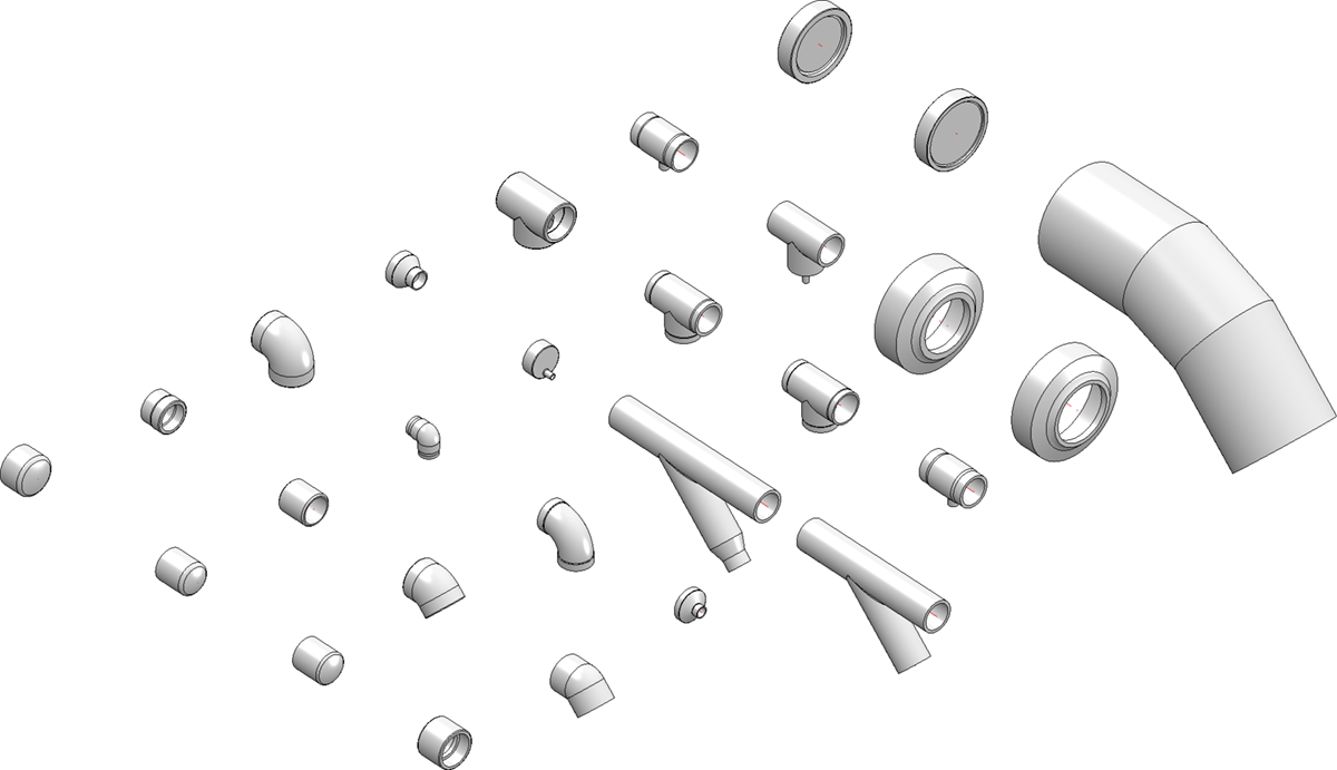
The parts are summarized in the list file PROGEF.lst. It contains the following variants:
|
File |
Designation |
Type |
|---|---|---|
|
PROGEF_BEND_45_SDR11.VAA |
Segment bend 45° SDR 11 |
Knee |
|
PROGEF_BEND_45_SDR17_6.VAA |
Segment bend 45° SDR 17.6 |
Knee |
|
PROGEF_CAP_COUPLER_SDR11.VAA |
Socket welded end cap SDR 11 |
Cap |
|
PROGEF_CAP_L_SDR11.VAA |
Butt welded end cap L SDR 11 |
Cap |
|
PROGEF_CAP_L_SDR17_6.VAA |
Butt welded end cap L SDR 17.6 |
Cap |
|
PROGEF_CAP_SDR11.VAA |
Butt welded end cap SDR 11 |
Cap |
|
PROGEF_CAP_SDR17_6.VAA |
Butt welded end cap SDR 17.6 |
Cap |
|
PROGEF_COUPLER_FUSION_SDR11.VAA |
Double socket SDR 11 |
Other pipe part |
|
PROGEF_COUPLER_REDUCER_FUSION_SDR11.VAA |
Socket welded reducer SDR11 |
Reducer, concentric |
|
PROGEF_DOUBLENIPPLE_FUSION_SDR11.VAA |
Socket welded double nipple SDR11 |
Other pipe part |
|
PROGEF_ELBOW_45_FUSION_SDR11.VAA |
Elbow 45° L SDR 11 socket welded |
Knee |
|
PROGEF_ELBOW_45_L_SDR11.VAA |
Elbow 45° L SDR 11 |
Knee |
|
PROGEF_ELBOW_90_FUSION_SDR11.VAA |
Elbow 90° socket welded SDR11 |
Knee |
|
PROGEF_ELBOW_90_SHORT_SDR11.VAA |
Elbow 90° short SDR11 |
Knee |
|
PROGEF_ELBOW_SWEEP_90_SDR11.VAA |
Elbow 90° SDR 11 |
Knee |
|
PROGEF_PIPE_SDR7_4.VAA |
PE100-Pressure pipe SDR7.4 |
Straight pipe |
|
PROGEF_PIPE_SDR11.VAA |
PE100-Pressure pipe SDR11 |
Straight pipe |
|
PROGEF_PIPE_SDR17_6.VAA |
PE100-Pressure pipe SDR17.6 |
Straight pipe |
|
PROGEF_REDUCER_BW_SDR11.VAA |
Butt welded reducer SDR 11 |
Reducer, concentric |
|
PROGEF_REDUCER_BW_SDR17_6.VAA |
Butt-welded reducer SDR 17.6 |
Reducer, concentric |
|
PROGEF_REDUCER_ECCENTRIC_SDR11.VAA |
Butt-welded reducer, eccentric SDR 11 |
Reducer, eccentric |
|
PROGEF_REDUCER_SHORT_BW_SDR11.VAA |
Butt welded reducer, short SDR 11 |
Reducer, concentric |
|
PROGEF_REDUCER_SHORT_BW_SDR17_6.VAA |
Butt welded reducer, short SDR 17.6 |
Reducer, concentric |
|
PROGEF_TEE_45_RED_SDR11.VAA |
T 45° reduced SDR 11 |
Branch |
|
PROGEF_TEE_45_SDR11.VAA |
T 45° equal SDR 11 |
Branch |
|
PROGEF_TEE_FUSION_SDR11.VAA |
T 90° SDR socket welded SDR 11 |
T-piece |
|
PROGEF_TEE_L_SDR11.VAA |
T 90° L SDR 11 |
T-piece |
|
PROGEF_TEE_L_SDR17_6.VAA |
T 90° L SDR 17.6 |
T-piece |
|
PROGEF_TEE_RED_MOLDED_SDR11.VAA |
T 90° reduced, molded SDR 11 |
T-piece |
|
PROGEF_TEE_RED_MOLDED_SDR17_6.VAA |
T 90° reduced, molded SDR 17.6 |
T-piece |
|
PROGEF_TEE_RED_REDUCER_SDR11.VAA |
T 90° butt welded reducer SDR11 |
T-piece |
ECOFIT
The parts inventory has been extended by parts from the manufacturer standard ECOFIT of the supplier Georg Fischer.
The parts are summarized in the list file ECOFIT.lst It contains the following variants:
|
File |
Designation |
Type |
|---|---|---|
|
ECOFIT_CAP_SDR11.VAA |
End cap SDR 11 |
Cap |
|
ECOFIT_COUPLER_REDUCER_SDR11.VAA |
Socket welded SDR 11 |
Other pipe part |
|
ECOFIT_DOUBLENIPPLE_SDR17.VAA |
Double nipple SDR 17 |
Other pipe part |
|
ECOFIT_ELBOW_11_SDR11.VAA |
Elbow 11° SDR 11 |
Knee |
|
ECOFIT_ELBOW_11_SDR17.VAA |
Elbow 11° SDR 17 |
Knee |
|
ECOFIT_ELBOW_22_SDR11.VAA |
Elbow 22° SDR 11 |
Knee |
|
ECOFIT_ELBOW_22_SDR17.VAA |
Elbow 22° SDR 17 |
Knee |
|
ECOFIT_ELBOW_30_SDR11.VAA |
Elbow 30° SDR 11 |
Knee |
|
ECOFIT_ELBOW_30_SDR17.VAA |
Elbow 30° SDR 17 |
Knee |
|
ECOFIT_ELBOW_45_SDR11.VAA |
Elbow 45° SDR 11 |
Knee |
|
ECOFIT_ELBOW_45_SDR17.VAA |
Elbow 45° SDR 17 |
Knee |
|
ECOFIT_ELBOW_60_SDR11.VAA |
Elbow 60° SDR 11 |
Knee |
|
ECOFIT_ELBOW_60_SDR17.VAA |
Elbow 60° SDR 17 |
Knee |
|
ECOFIT_ELBOW_90_SDR11.VAA |
Elbow 90° SDR 11 |
Knee |
|
ECOFIT_ELBOW_90_SDR17.VAA |
Elbow 90° SDR 17 |
Knee |
|
ECOFIT_ELBOW_SHORT_45_SDR11.VAA |
Elbow 45° SDR 11, kurz |
Knee |
|
ECOFIT_ELBOW_SHORT_90_SDR11.VAA |
Elbow 90° SDR 11, kurz |
Knee |
|
ECOFIT_INSERT_COMPONENT_SDR11.VAA |
Bolting insert SDR 11 |
Flange |
|
ECOFIT_INSERT_COMPONENT_SDR17.VAA |
Bolting insert SDR 11 |
Flange |
|
ECOFIT_LOOSEFLANGE_SDR11.VAA |
Loose flange, butt welded SDR 11 |
Flange |
|
ECOFIT_LOOSEFLANGE_SDR17.VAA |
Loose flange, butt welded SDR 17 |
Flange |
|
ECOFIT_ORING.VAA |
O-ring gasket |
Seal |
|
ECOFIT_PIPE_SDR11.VAA |
PE100 pressure pipe SDR 11 |
Straight pipe |
|
ECOFIT_PIPE_SDR17.VAA |
PE100 pressure pipe SDR 17 |
Straight pipe |
|
ECOFIT_PIPE_SDR17-FM.VAA |
PE100 pressure pipe SDR 17, FM |
Straight pipe |
|
ECOFIT_PIPE_SDR41.VAA |
PE100 pressure pipe SDR 41 |
Straight pipe |
|
ECOFIT_PIPE_SDR7_4.VAA |
PE100 pressure pipe SDR 7.4 |
Straight pipe |
|
ECOFIT_REDUCER_BW_SDR11.VAA |
Butt welded reducer SDR 11 |
Reducer, concentric |
|
ECOFIT_REDUCER_BW_SDR17.VAA |
Butt welded reducer SDR 17 |
Reducer, concentric |
|
ECOFIT_REDUCER_SHORT_BW_SDR11.VAA |
Butt welded reducer SDR 11, short |
Reducer, concentric |
|
ECOFIT_REDUCER_SHORT_BW_SDR17.VAA |
Butt welded reducer SDR 17, short |
Reducer, concentric |
|
ECOFIT_SCREW_FITTING_SDR11.VAA |
Bolting screw-in part SDR 11 |
Flange |
|
ECOFIT_SCREW_FITTING_SDR17.VAA |
Bolting screw-in part SDR 17 |
Flange |
|
ECOFIT_STUB_FLANGE_A_SDR17.VAA |
Butt welded collar Type A SDR 17 |
Flange |
|
ECOFIT_STUB_FLANGE_B_SDR17.VAA |
Butt welded collar Type B SDR 17 |
Flange |
|
ECOFIT_TEE_45_SDR11.VAA |
T 45° equal SDR 11 |
Branch |
|
ECOFIT_TEE_45_SDR17.VAA |
T 45° equal SDR 17 |
Branch |
|
ECOFIT_TEE_RED_45_SDR11.VAA |
T 45° reduced SDR 11 |
Branch |
|
ECOFIT_TEE_RED_REDUCER_SDR11.VAA |
T 90° butt welded reducer SDR 11 |
T-piece |
|
ECOFIT_TEE_RED_REDUCER_SDR17.VAA |
T 90° butt welded reducer SDR 17 |
T-piece |
|
ECOFIT_TEE_RED_SHORT_SDR11.VAA |
T 90° reduced SDR 11, short |
T-piece |
|
ECOFIT_TEE_RED_SHORT_SDR17.VAA |
T 90° reduced SDR 17, short |
T-piece |
|
ECOFIT_TEE_SHORT_SDR11.VAA |
T 90° SDR 11, short |
T-piece |
|
ECOFIT_TEE_SHORT_SDR17.VAA |
T 90° SDR 17, short |
T-piece |
|
ECOFIT_UNION_NUT.VAA |
Bolting - union nut |
Fastener, unsymmetric |
ELGEF
The parts inventory has been extended by parts from the manufacturer standard ECOFIT of the supplier Georg Fischer.
The parts are summarized in the list file ELGEF.lst It contains the following variants:
|
File |
Designation |
Type |
|---|---|---|
|
ELGEF_BEND_45_SDR11.VAA |
Segment bend 45° SDR 11 |
Knee |
|
ELGEF_BEND_45_SDR17.VAA |
Segment bend45° SDR 17 |
Knee |
|
ELGEF_BEND_60_SDR11.VAA |
Segment bend60° SDR 11 |
Knee |
|
ELGEF_BEND_60_SDR17.VAA |
Segment bend60° SDR 17 |
Knee |
|
ELGEF_BEND_90_SDR11.VAA |
Segment bend90° SDR 11 |
Knee |
|
ELGEF_BEND_90_SDR17.VAA |
Segment bend90° SDR 17 |
Knee |
|
ELGEF_CAP_L_SDR11.VAA |
End cap Type L SDR 11 |
Cap |
|
ELGEF_CAP_L_SDR17.VAA |
End cap Type L SDR 17 |
Cap |
|
ELGEF_CAP_SDR11.VAA |
End cap SDR 11 |
Cap |
|
ELGEF_COUPLER_SDR11.VAA |
Socket SDR 11 |
Other pipe part |
|
ELGEF_COUPLER_SDR17.VAA |
Socket SDR 17 |
Other pipe part |
|
ELGEF_COUPLER_SDR26.VAA |
Socket SDR 26 |
Other pipe part |
|
ELGEF_ELBOW_45_SDR11.VAA |
Elbow 45° SDR 11 |
Knee |
|
ELGEF_ELBOW_90_SDR11.VAA |
Elbow 90° SDR 11 |
Knee |
|
ELGEF_ELBOW_L_15_SDR11.VAA |
Elbow 15° Typ L SDR 11 |
Knee |
|
ELGEF_ELBOW_L_15_SDR17.VAA |
Elbow 15° Typ L SDR 17 |
Knee |
|
ELGEF_ELBOW_L_30_SDR11.VAA |
Elbow 30° Typ L SDR 11 |
Knee |
|
ELGEF_ELBOW_L_30_SDR17.VAA |
Elbow 30° Typ L SDR 17 |
Knee |
|
ELGEF_ELBOW_L_45_SDR11.VAA |
Elbow 45° Typ L SDR 11 |
Knee |
|
ELGEF_ELBOW_L_45_SDR17.VAA |
Elbow 45° Typ L SDR 17 |
Knee |
|
ELGEF_ELBOW_L_90_SDR11.VAA |
Elbow 90° Typ L SDR 11 |
Knee |
|
ELGEF_ELBOW_L_90_SDR17.VAA |
Elbow 90° Typ L SDR 17 |
Knee |
|
ELGEF_REDUCER_BW_SDR11.VAA |
Butt welded reducer SDR 11 |
Reducer, concentric |
|
ELGEF_REDUCER_BW_SDR17.VAA |
Butt welded reducer SDR 17 |
Reducer, concentric |
|
ELGEF_REDUCER_SDR11.VAA |
Reducer SDR 11 |
Reducer, concentric |
|
ELGEF_SPIGOT_CLAMP_SDR11.VAA |
Spigot clamp SDR 11 |
Saddle connection |
|
ELGEF_TEE_DRILL_SDR11.VAA |
T 90° tapping-T SDR 11 |
Corner valve |
|
ELGEF_TEE_L_SDR11.VAA |
T 90° Type L SDR 11 |
T-piece |
|
ELGEF_TEE_RED_SADDLE.VAA |
T 90° saddle connection reduced SDR 11 |
T-piece |
|
ELGEF_TEE_RED_SDR11.VAA |
T 90° reduced SDR 11 |
T-piece |
|
ELGEF_TEE_SDR11.VAA |
T 90° SDR 11 |
T-piece |
Polyethylene pipes acc. to DIN 8074
The parts inventory was extended by polyethylene pipes according to DIN 8074. The parts are summarized in the list file N8074.lst. It contains the following variants:
|
File |
Designation |
Type |
|---|---|---|
|
N8074_SDR11.VAA |
PE 100 pressure pipe |
Straight pipe |
|
N8074_SDR17.VAA |
PE 100 pressure pipe |
Straight pipe |
|
N8074_SDR17_6.VAA |
PE 100 pressure pipe |
Straight pipe |
|
N8074_SDR26.VAA |
PE 100 pressure pipe |
Straight pipe |
|
N8074_SDR33.VAA |
PE 100 pressure pipe |
Straight pipe |
|
N8074_SDR7_4.VAA |
PE 100 pressure pipe |
Straight pipe |
Isometry and pipe spool drawing
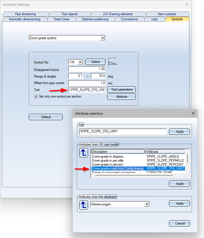
Down-grade symbol
In the Configuration Editor, the unit for the display of the down-grade symbol can now be selected. In addition, only one setting option for the number of decimal places is now available there.
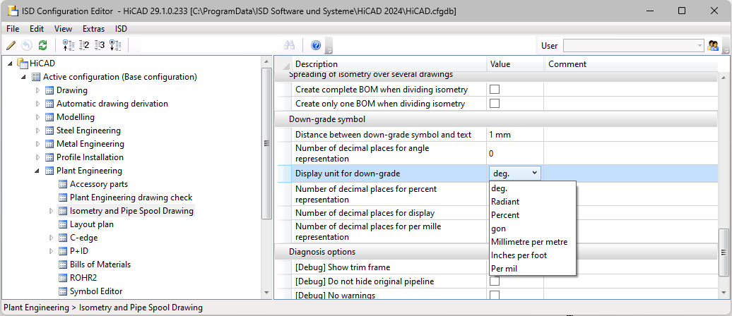
In the isometry/pipe spool drawing settings for down-grade symbols (open the Symbols tab), the new text key %PIPE_SLOPE_CFG_UNIT can be used to display the unit of the down-grade symbol in the isometry according to the unit specified in the Configuration Editor.
Units in the isometry and pipe spool drawing settings
Different units are now also supported in the settings for isometry and pipe spool drawing. This means that in many cases the mm display is no longer shown in the dialogues, e.g.
The values can be entered in any desired unit and are then automatically converted into the unit of measurement preset in the Configuration Editor. If you point the cursor at the  symbol, the preset unit is displayed.
The font height of the dimension figure must be specified in mm.
Generate pipe book
As of HiCAD 2024 SP1, so-called pipe books can be generated for isometries or pipe spool drawings. To do this, go to Isometry+Pipe Spool Drawing > Edit lists > EditPL >... and choose the new the new Pipe book function.
A pipe book - also known as a weld book or weld seam book - is a special bill of materials that contains all relevant information about weld seams and parts of a pipeline. This includes part information such as standards and dimensions, detailed information on the material, the weld seam and the welding process.
Microsoft® Excel is required for creating a pipe book.
An isometry or pipe spool drawing must be available to generate a pipe book. This is necessary because the item numbers of the welded joints are required for the pipe book and these are only assigned in HiCAD when the isometry or pipe spool drawing is generated.
After calling up the Pipe book function, the Report Manager is automatically started with a corresponding quantity list. This quantity list is the basis for the pipe book. You then generate the pipe book itself in the Report Manager using the Create Excel document (with template or script)  function.
The process is described below using the example shown for an isometry.
Step 1: Create the isometry
Step 2: Generate a quantity list for the pipe book
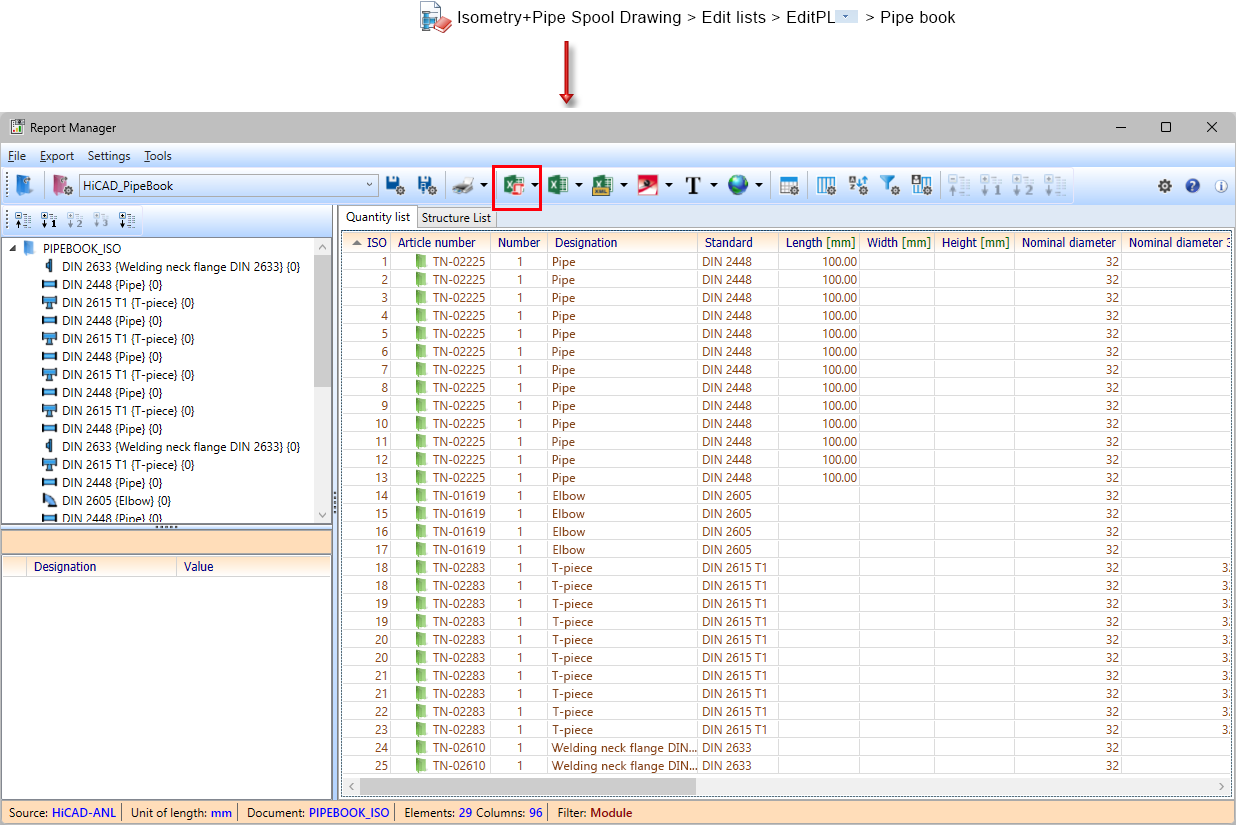
Step 3: Create the Excel document
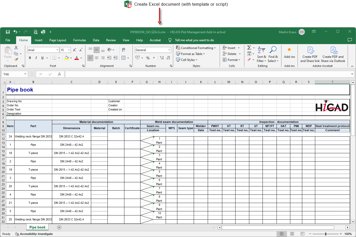
The pipe book itself can be understood as a two-part list. The pipe parts are on the left and the weld seams on the right. Each weld seam is located between two pipe parts, which is indicated in the table by the opening wedges between the two areas.
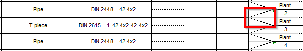
The table is built up section by section, with the pipe parts on the sections following the direction of flow. Accordingly, parts can occur several times. To make this clearer in the example above, the identical part search has been switched off so that each pipe part has its own item number. This means that you can find the T-pieces with item numbers 18, 19, 20 and 21 twice. The example isometry consists of three sections; the gaps in the column with the weld seam items indicate the start of the next section.
The files listed below, which are all located in the HiCAD sys directory, are relevant for creating the pipe book.
|
HiCAD_PipeBook.DE.2901.0.xlsx |
The document template for creating the pipe book in Excel. |
|
HiCAD_PipeBook.2901.0.cs |
A C# script that fills the Excel template with the data from the Report Manager. |
|
HiCAD_PipeBook.rm_settings |
The settings for the Report Manager. Here it is specified that the above Excel template and the above C# script should be used. |
|
rm_anl_exportpart_pipebook.hdb |
Defines the data that HiCAD transfers to the Report Manager. |
Pipeline Tools
Calculate transition
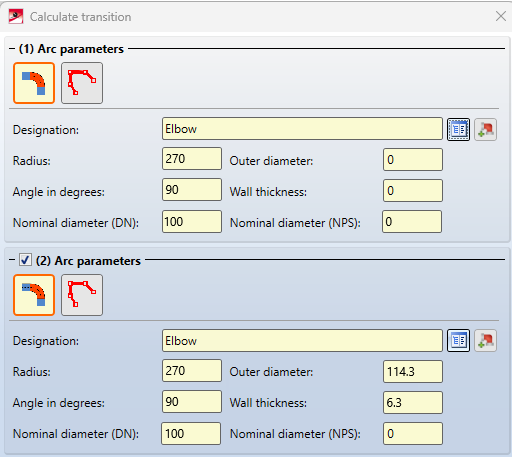
The NPS nominal diameter is now also displayed in the dialogue for the Calculate transition function.
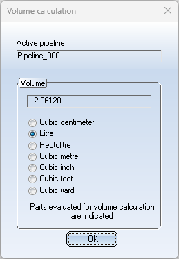
Determine volume
Imperial units are now also available for selection in the Determine volume function.
Guideline Editor
As of SP1, the former Guideline Editor displays the coordinates in the unit selected in the Configuration Editor. In addition, the grid size can be specified here in any unit of length. It is then automatically converted into the preset unit.
Major Release 2024 (V 2900)
Component connections with flange parameters
Component connections now also support flange parameters. This makes flanging possible on parts imported via the STEP interface.
The dialogue for creating and editing component connections has been expanded accordingly.
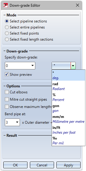
Down-grade Editor - more units
The specification of down-grades in the Down-grade Editor can now also be done in Radiant, Gon, mm/m, in/ft and per mil.
Isometry and pipe spool drawing
Generate pipe spool drawing from Sheet view
If pipe spool drawings are created in a Sheet area of the active drawing and then a pipe spool drawing is created again from this Sheet view, then exactly those parts are taken into account in the new/updated pipe spool drawing that were also visible in the original Sheet view. This means that in this case you will not be asked to select the parts for the pipe spool drawing.
If the pipe spool drawing is generated from the Model view, then you must select the parts. Unless you have deactivated the checkbox Part selection before displaying pipe spool drawing dialogue in the Configuration Editor at Plant Engineering > Isometry and Pipe Spool Drawing.
Changed default settings during isometry/pipe spool drawing creation
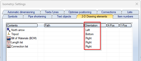
Orientation of 2-D drawing elements
The previous default settings for the orientation of the 2-D drawing elements of an isometry/pipe spool drawing led to the following message being displayed during a new installation:
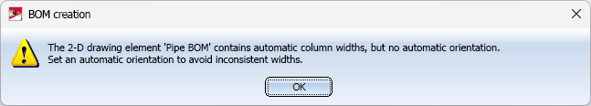
As of HiCAD 2024, these default settings are such that the message no longer appears.
Data record assignment for the connection type
From HiCAD 2024 onwards, a data set assignment is automatically made for all connection types, provided that the default articles are available in the HELiOS database.
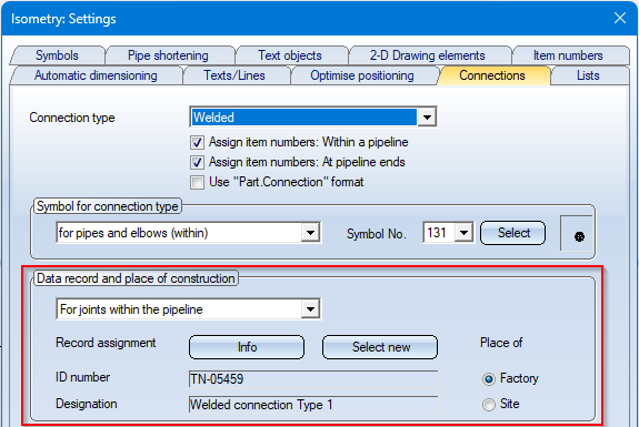
This prevents the following message from appearing:
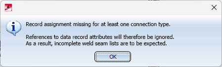
The message will only appear if an automatic assignment is not possible due to missing default articles.
Part insertion
Seach with unit
The function Pipe parts now also supports the specification of units when searching for attributes, e.g.

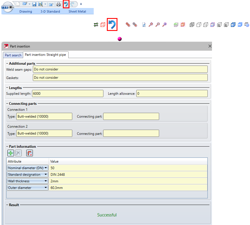
Insert connection pieces
When using the part insertion with the function Pipe parts , the placing of connecting pieces between straight pipes can now be switched on or off. For this purpose, the Settings area of the Straight pipes tab has been extended accordingly.
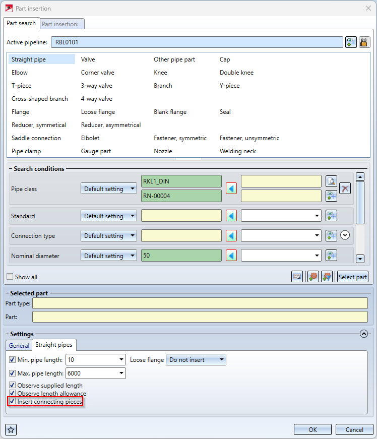
If the checkbox Insert connecting pieces is active here, the connecting pieces specified in the Plant Engineering Settings for Straight pipes are automatically inserted when straight pipes are inserted.
If no connecting pieces are preselected in the Plant Engineering Settings, this is indicated by the  symbol in the Part insertion dialogue window.
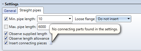
Please note:
Connecting pieces are also inserted if the checkbox in the Plant Engineering settings for straight pipes is deactivated, but activated for part insertion.
Changed buttons
In the Part insertion dialogue window, the button for part selection has been replaced:

Part data synchronisation
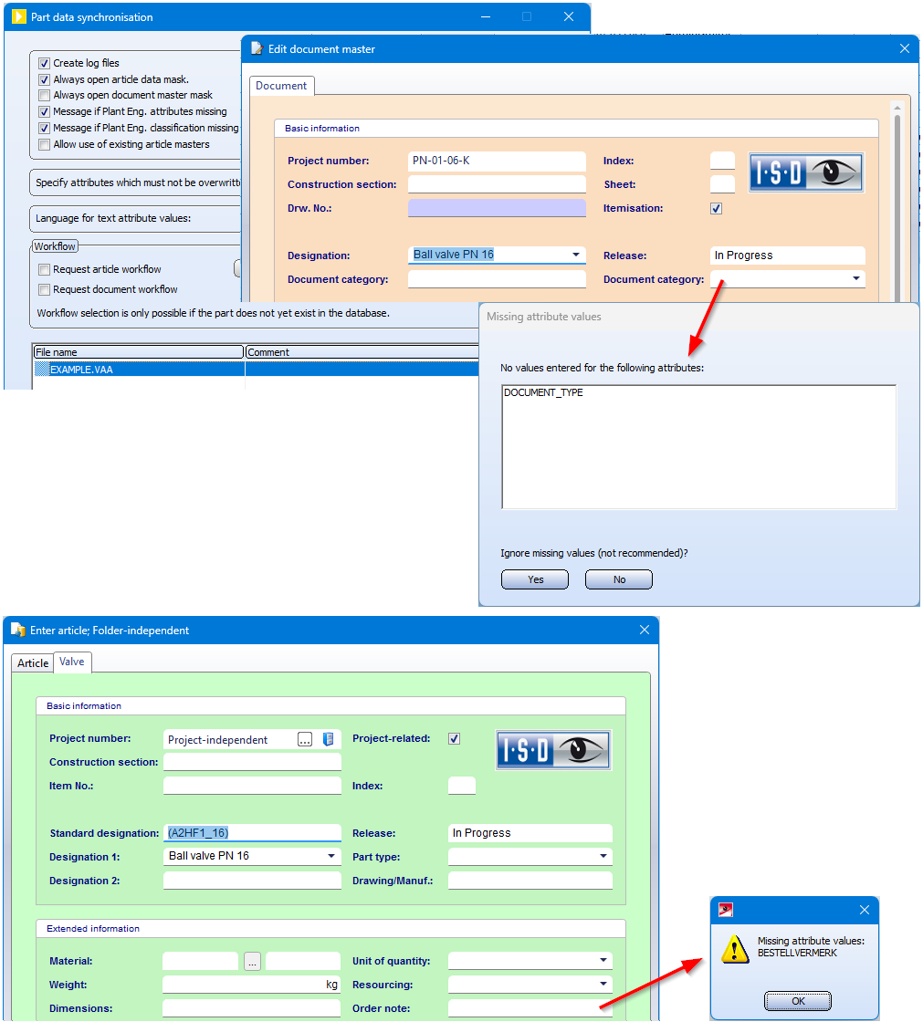
Indication of missing attributes
If mandatory attributes in the document or article master are missing during part data synchronisation, for example the document type (DOCUMENT_TYPE) or the order note (BESTELLVERMERK), HiCAD will now indicate this. You then have the possibility to enter the missing attributes. In the case of the document master, you can create it - as before - despite missing attributes, but this is not possible with missing article attributes.
Derived variants with different attributes
If variants are derived on the HELiOS side with the Variant Editor (file selection: with database via document/article master) and attributes of the general type - for example, the material - are changed in the process, then these attributes are not overwritten with the value from the original variant during a data synchronisation.
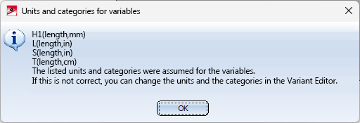
Synchronisation with catalogue - Units and categories
When synchronising part data with the HiCAD catalogue, from HiCAD 2024 it is also possible to select and transfer units and categories when assigning attributes, e.g.:
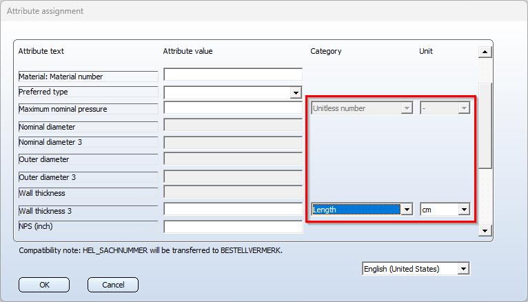
The attributes that expect a Unitless number are all Nominal diameter (NENNWEITE) attributes and the attribute Pressure (DRUCK).
Create pipeline - Assigning of nominal diameters
When creating a new pipeline, you must now choose between the nominal diameters DN (for nominal diameters that correspond approximately to mm) and NPS (for nominal diameters that are applied to inches). This also applies if the option Assign nominal diameter is not selected. This selection DN or NPS determines the nominal diameter that will later be included in the search for automatically found search conditions.
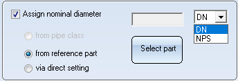
When using the new Part insertion function, the nominal diameters can be found in the search as shown:
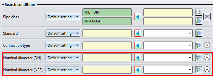
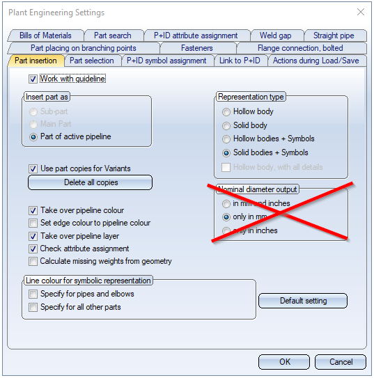
Since the nominal diameter type must now be selected when creating a pipeline, the selection of the nominal diameter output is omitted on the Part insertion tab in the Plant Engineering Settings dialogue window.
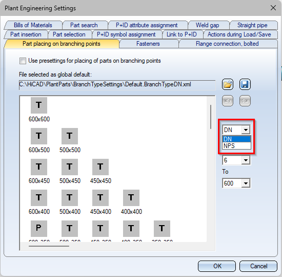
Instead, a selection box for the nominal diameter has been added to the tab Part placing on branching points.
Important:
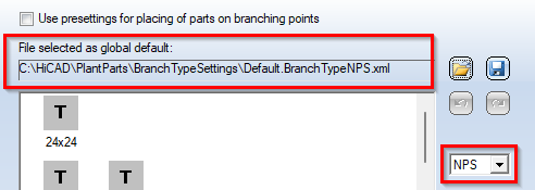
If you select NPS, the file selected for global presetting must also be adapted to NPS, i.e. you must select a corresponding settings file. In the PlantParts\BranchTypeSettings directory of your HiCAD installation, for example, the Default.BranchTypeNPS.xml file is available for NPS nominal diameters.
Files managed by HELiOS
HiCAD cannot determine where the data originates when accessing files for which a document master exists. This can lead to problems when dealing with variants.
For example, a variant could be loaded from the hard disk in the Variant Editor, modified and transferred to the corresponding items in HELiOS with the part data synchronization. In fact, this variant file can be managed by HELiOS e.g. in the Vault Server. So one has not changed the file to which the document master actually points.
This means that when the variant is installed, potentially a different geometry is calculated than expected, because the selected item no longer matches the expression in the VAA file to which the document master points.
Therefore, when a file is opened via the file system, it is checked whether this file is managed by HELiOS. If this is the case, the following message appears:
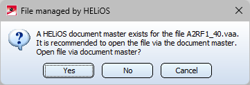
If you click on Yes, the file will be loaded via the document master. This ensures that the file matches the one in the document master.
This query also appears when opening takes place via the file system
- in the PAA Editor (AnPaaEdit.exe),
- during part data synchronization (PartDataAutoSync.exe), and
- during the configuration of the HELiOS database (DBPlantDataImport.exe).
- in the Variant Editor (Varienteneditor.exe)
Create feature variant - Units
When creating a feature variant, the assigned units are now taken into account and you are informed about the accepted units.
PAA Editor - Units and Categories
When creating and editing PAA archives, from HiCAD 2024 units and categories can also be selected and transferred during attribute assignment, e.g.
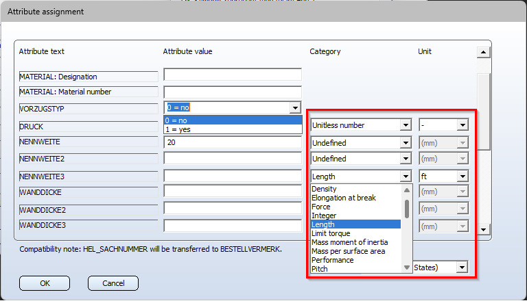
The attributes that expect a unitless number are all Nominal diameter attributes and the Pressure attribute.
Jacob Push-in pipes - Length and Weight
From HiCAD 2024 onwards, Jacob Push-in pipes receive their delivery length as a length attribute. The delivery length is now also no longer adjusted by the dynamic route change.
In the variant files of these push-in pipes, the attribute Arbitrarily divisible (BELIEBIG_TEILBAR) is set to 0=No.
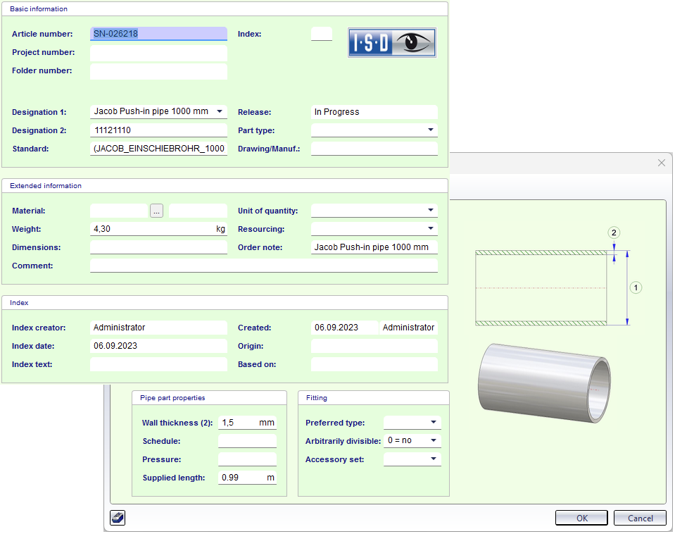
In addition, the attribute Weight for Jacob push-in pipes is also taken directly from the database and is no longer interpreted as weight per metre as with other straight pipes.
Check for invalid nominal diameter matings
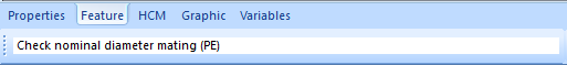
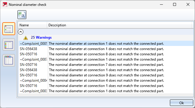
While the check for nominal diameter matings is running, the message Check nominal diameter mating (PE) is now displayed in the HiCAD status bar.
This applies to the functions:
 Check for invalid nominal diameter matings (active pipeline) and
 Check for invalid nominal diameter matings (entire drawing)
as well as the automatic check when opening and saving Plant Engineering drawings.
If errors are found, a list of parts whose connections have different nominal diameters is also displayed, e.g.:
New versions of the EN 1092-1 flanges
The loose flanges and plane flanges of the EN 1092-1 standard were not clearly recognisable as such until now. This has been improved in HiCAD 2024 by a revision and renaming.
|
Plane flanges |
|
|---|---|
|
previously |
from HiCAD 2024 |
|
EN1092-1-01-PN10.vaa |
EN1092-1-01-PN100_SF.vaa |
|
EN1092-1-01-PN100.vaa |
EN1092-1-01-PN10_SF.vaa |
|
EN1092-1-01-PN16.vaa |
EN1092-1-01-PN16_SF.vaa |
|
EN1092-1-01-PN25.vaa |
EN1092-1-01-PN25_SF.vaa |
|
EN1092-1-01-PN2_5.vaa |
EN1092-1-01-PN2_5_SF.vaa |
|
EN1092-1-01-PN40.vaa |
EN1092-1-01-PN40_SF.vaa |
|
EN1092-1-01-PN6.vaa |
EN1092-1-01-PN63_SF.vaa |
|
EN1092-1-01-PN63.vaa |
EN1092-1-01-PN6_SF.vaa |
|
Looose flanges |
|
|---|---|
|
previously |
from HiCAD 2024 |
|
EN1092-1-02-32-PN10.vaa |
EN1092-1-02-32-PN10_LF.vaa |
|
EN1092-1-02-32-PN16.vaa |
EN1092-1-02-32-PN16_LF.vaa |
|
EN1092-1-02-32-PN25.vaa |
EN1092-1-02-32-PN25_LF.vaa |
|
EN1092-1-02-32-PN2_5.vaa |
EN1092-1-02-32-PN2_5_LF.vaa |
|
EN1092-1-02-32-PN40.vaa |
EN1092-1-02-32-PN40_LF.vaa |
|
EN1092-1-02-32-PN6.vaa |
EN1092-1-02-32-PN6_LF.vaa |
|
EN1092-1-02-35-PN10.vaa |
EN1092-1-02-35-PN10_LF.vaa |
|
EN1092-1-02-35-PN16.vaa |
EN1092-1-02-35-PN16_LF.vaa |
|
EN1092-1-02-35-PN25.vaa |
EN1092-1-02-35-PN25_LF.vaa |
|
EN1092-1-02-35-PN2_5.vaa |
EN1092-1-02-35-PN2_5_LF.vaa |
|
EN1092-1-02-35-PN40.vaa |
EN1092-1-02-35-PN40_LF.vaa |
|
EN1092-1-02-35-PN6.vaa |
EN1092-1-02-35-PN6_LF.vaa |
|
EN1092-1-02-36-PN10.vaa |
EN1092-1-02-36-PN10_LF.vaa |
|
EN1092-1-02-36-PN16.vaa |
EN1092-1-02-36-PN16_LF.vaa |
|
EN1092-1-02-36-PN2_5.vaa |
EN1092-1-02-36-PN2_5_LF.vaa |
|
EN1092-1-02-36-PN6.vaa |
EN1092-1-02-36-PN6_LF.vaa |
|
EN1092-1-02-37-PN10.vaa |
EN1092-1-02-37-PN10_LF.vaa |
|
EN1092-1-02-37-PN16.vaa |
EN1092-1-02-37-PN16_LF.vaa |
|
EN1092-1-02-37-PN2_5.vaa |
EN1092-1-02-37-PN2_5_LF.vaa |
|
EN1092-1-02-37-PN6.vaa |
EN1092-1-02-37-PN6_LF.vaa |
|
EN1092-1-04-34-PN10.vaa |
EN1092-1-04-34-PN10_LF.vaa |
|
EN1092-1-04-34-PN16.vaa |
EN1092-1-04-34-PN16_LF.vaa |
|
EN1092-1-04-34-PN25.vaa |
EN1092-1-04-34-PN25_LF.vaa |
|
EN1092-1-04-34-PN40.vaa |
EN1092-1-04-34-PN40_LF.vaa |
New masks for part search in Plant Engineering
Due to the differentiation between the nominal diameters DN (for nominal diameters that correspond approximately to mm) and NPS (for nominal diameters that are applied to inches), the HELiOS search masks for the part search in Plant Engineering have also been adapted accordingly, e.g.
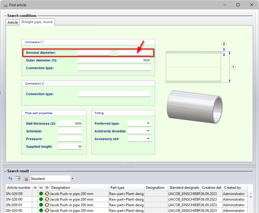
In the right field, which is used to search for the nominal diameter in inches (NPS), an entry in floating point numbers is now expected, e.g. "2 instead of 2". This affects all search masks for parts in which the attribute Nominal diameter is available in this form..
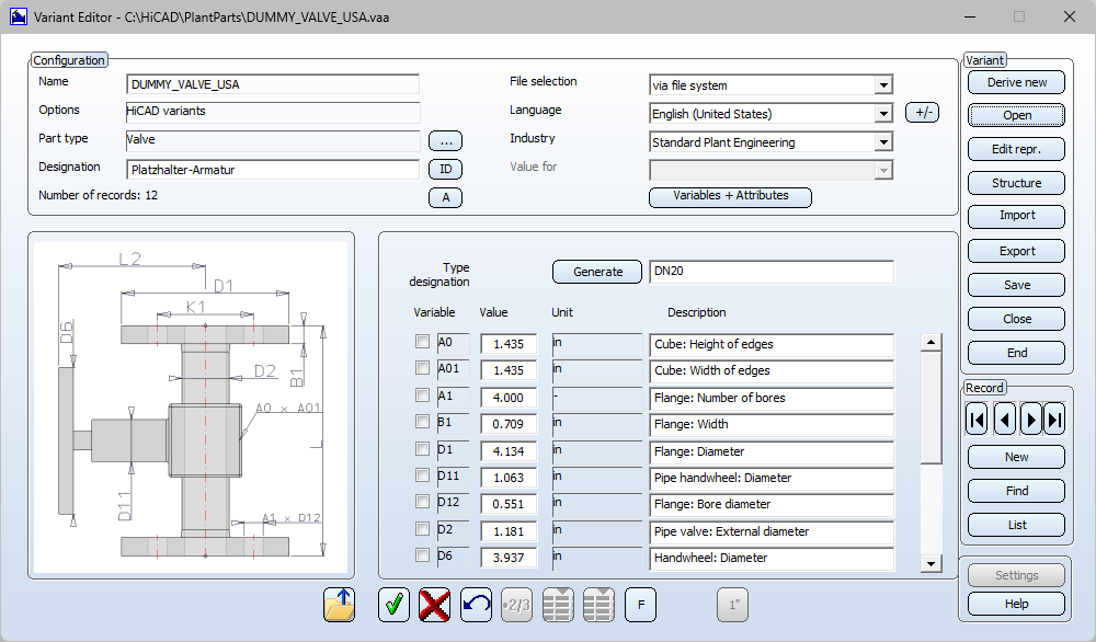
Placeholders in imperial units
When inserting placeholders, units can now be used.
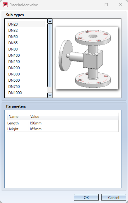
The following variants are available for this purpose in the PlantParts directory of the HiCAD installation:
- DUMMY_VALVE.VAA (metric units, stored in mm) and
- DUMMY_VALVE_USA.VAA (imperial units, stored in inches).