Select Pipeline
Plant Engineering > Isometry/Pipe Spool Drawing > Auto-generate drawing 
Plant Engineering > Isometry/Pipe Spool Drawing > Generate pipe spool drawing 
Isometry + Pipe spool drawing > Create > Auto-generate drawing 
Isometry
After calling the function the Plant Engineering Isometry dialogue window is displayed. On the left side of the dialogue window all pipelines of the current model drawing are listed and the corresponding checkboxes are activated.
Alternatively, the function can also be called via the context menu for pipelines. In this case only the checkbox of the pipeline active when the function is called will be activated.
In addition, you can select several pipelines in model drawing and then use the right mouse button to open the Multiple selection context menu.
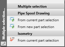
If you select the Isometry - From current part selection function there, the checkboxes of all pipelines belonging to the selection are active in the Plant Engineering Isometry dialogue window.
The function is also available in the Isometry context menu, which you can activate by right-clicking on a pipe.
Pipe spool drawing
Furthermore, all pipelines in the current drawing are listed on the left side of the Pipe spool drawing dialogue window. Here, only the checkboxes of the pipelines belonging to the previously selected parts are active.

Alternatively, the generation of pipe spool drawings can be activated via the context menu for pipelines or, in the case of several pipelines, selected in the model drawing, via the Multiple selection context menu.
In this case, the following options are available:
-
From current part selection
The Pipe Spool Drawing dialogue window is displayed directly here.
-
From new part selection
Here you have the option of adjusting the selection again.
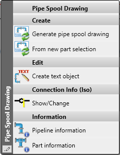
These functions are also available in the Pipe Spool Drawing context menu, which you activate by right-clicking on a pipe in the pipe spool drawing. This allows you to create further pipe spool drawings directly from the loaded pipe spool drawing.
Please note:
If pipe spool drawings are created in a Sheet area of the active drawing and then a pipe spool drawing is created again from this Sheet view, then exactly those parts are taken into account in the new/updated pipe spool drawing that were also visible in the original Sheet view. This means that in this case you will not be asked to select the parts for the pipe spool drawing. If the pipe spool drawing is generated from the Model view, then you must select the parts. Unless you have deactivated the checkbox Part selection before displaying pipe spool drawing dialogue in the Configuration Editor at Plant Engineering > Isometry and Pipe Spool Drawing.
Select pipelines
If necessary, in the Plant Engineering Isometry or Pipe Spool Drawing dialogue window, select the pipelines to be processed. The following options are available for this purpose:
Select/ deselect via mouse click
Select the desired pipelines via double-click on the corresponding list item.
Pick pipeline
Click on this button to select the desired pipelines in the drawing. Right-click to get back to the dialogue window.
Select / deselect all
Click on the button to select or deselect all pipelines in one step.
Link / Cut
HiCAD offers the option to combine several pipelines into a set, which will then be regarded as "one" pipeline when generating the isometry or the pipe spool drawing. Since you can freely define such pipeline sets, you are enabled to separate you model drawing into pipelines in a more flexible way and without having to have the drawing generation already in the back of your mind.
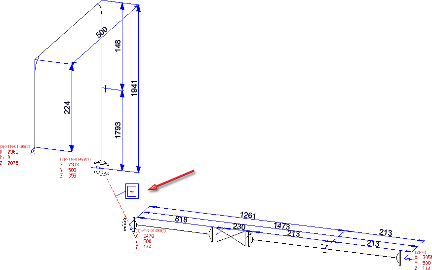
The decisive difference between the drawing of a pipeline set and the drawing of a separate pipeline is that the points where the pipelines of a set converge will be interpreted as inner points of a pipeline. Chain dimensions span these points and connecting points are marked accordingly; no annotation tags with connection coordinates will be created.
In an isometry, attention is paid to the question whether the set is continuous. If required, distance elements will be created and marked with by a tilde ~:
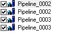
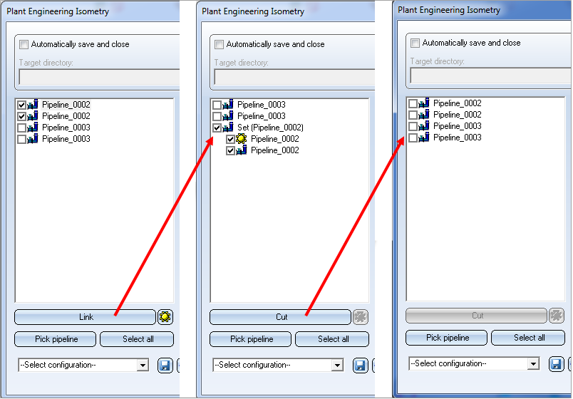
To define a pipeline set, simply select the pipelines you want to combine into a set and click on the Link button. The selected pipelines will then be merged into a set in the list, and will automatically obtain the name Set, followed by the name of the main pipeline in brackets, e.g. Set (Pipeline_0002).
The Link button is context-sensitive. When you select a pipeline set, the name of the "Link" button will change to Cut. Click the Cut button to split the set up into the individual pipelines again.
The main pipeline is marked with the  symbol. The purposes of the main pipeline in the isometry and pipe spool drawing are as follows:
- The dimensioning is assigned to the main pipeline (or, in the isometry, to the copy of the main pipeline).
- The coordinate system that was defined in the layout plan with the Alignment of derived drawings function will be taken over by the main pipeline.
- The optionally defined Reference Coordinate system will also be taken over by the main pipeline.
- If the drawing is created in a new model drawing, the name of the created new model drawing will be based on the name of the main pipeline. This allows you to create the same drawing multiple times with the parameters of different main pipelines, preventing any conflicts between names.
- The link between layout plan and isometry/pipe spool drawing that is evaluated by the Linked documents function, is also established via the main pipeline.
You can use the  icon to make a different pipeline the main pipeline of the set.
![]() Please note:
Please note:
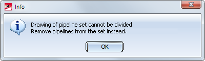
- After creating the isometry of the pipeline set, it will not be possible to spread this isometry over several pages subsequently. When you call the function Isometry+Pipe Spool Drawing > Settings > Specify division
 , the following message will be displayed:
- Together with the Divide pipeline
 function the use of pipeline sets is a flexible possibility to arrange isometries or pipe spool drawings appropriately.


Generate Isometry / Pipe Spool Drawing (PE/Iso) • Isometry and Pipe Spool Drawing (PE/Iso) • Isometry and Pipe Spool Drawing Functions for the Layout Plan (PE)