Isometry + Pipe Spool Drawing > Finishing > Update > Recolour pipe part symbols
The colour of the symbolic representation in the isometry is defined when a pipe part is inserted. The corresponding Plant Engineering Settings on the Part insertion tab are taken into account in the process.
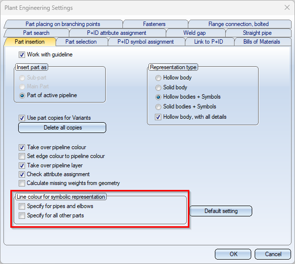
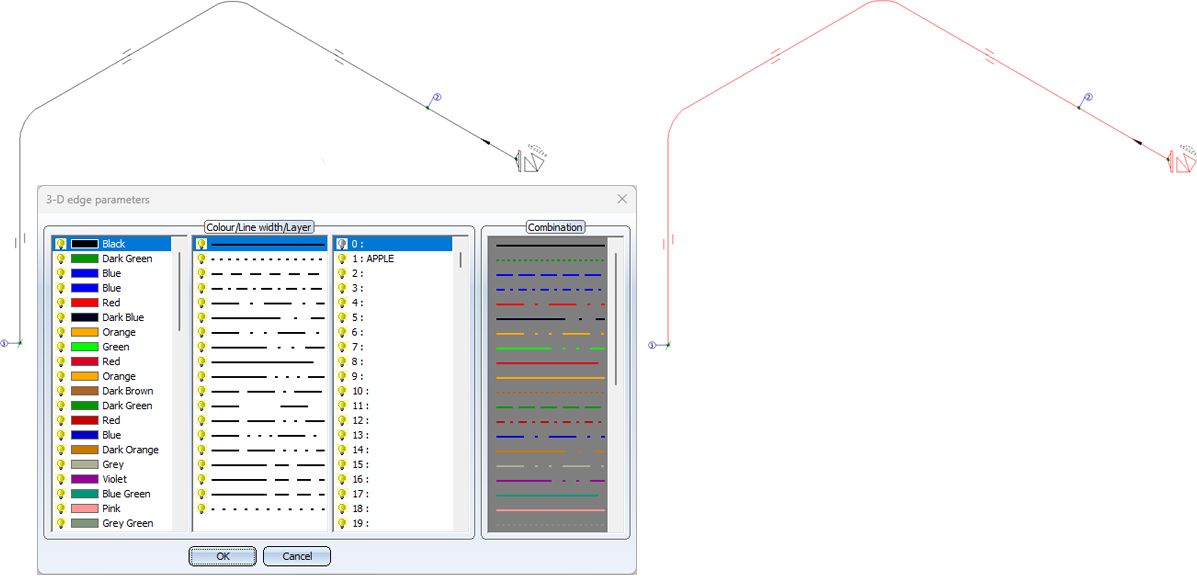
Sometimes, however, it only becomes apparent later that the colour or line type of the symbolic representations should be changed. Particularly when printing, there is often a desire to differentiate the pipework from other drawing elements - such as dimensions - in the visualisation. Previously, the colour of the symbols had to be laboriously adjusted by hand. As of SP2, this is now possible in a single step with the Recolour pipe part symbols function. To do this, the 3-D edge parameters window is opened after calling up the function. Immediately after selecting the desired parameters, they change colour in the isometry.
![]() Please note:
Please note:
- In particular, symbols such as weld seams, flow symbols or even indicated parts are not recoloured. Dimensionings and rise triangles also retain their colour.
- The function is a post-processing step. This means that the colour is only changed for the current isometry. In particular, the colour is reset to the original colour when the isometry is regenerated.
- As only one crosshairs and one north arrow are generated, you may need to move both figures on the sheet using the 2-D part > Transform > Move > Move part, free (2-D) function.


Isometry and Pipe Spool Drawing (PE/Iso) • Isometry/Pipe Spool Drawing Functions for the Layout Plan • The "Plant Engineering" Tab