The Pipe parts function
Plant Engineering > New > Pipe parts 
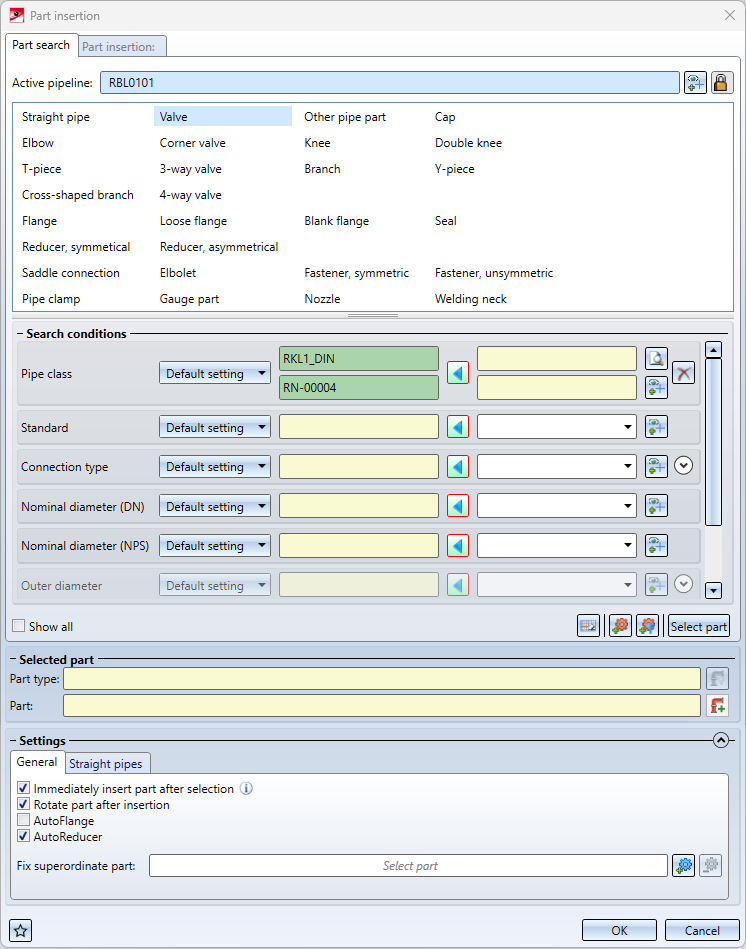
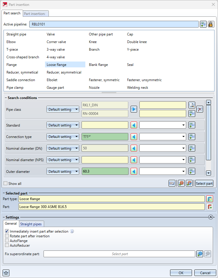
Pipe parts are parts that can be part of a pipeline. They can be aligned and positioned using guidelines. The dialogue shown is displayed for the insertion of pipe parts. In this dialogue window you have full control over which search criteria are used to search for a part.
This function is also available in the context menus for guidelines and Plant Engineering parts.

Part search
Active pipeline
The name of the active pipeline is displayed in the upper area of the tab. Newly added parts will be subordinated to this pipeline, provided there is nothing to the contrary, e.g. the placing of a part on a guideline. In such a case, the part must be assigned to the same pipeline as the guideline.
You can change the active pipeline within the dialogue. To do this, click on the  symbol and then select a pipeline in the drawing or in the ICN.
If you click in the name field, the active pipeline is highlighted in the drawing. Clicking again removes the highlighting.
Displaying and selecting the active pipeline in the dialogue makes it easier to connect parts to existing pipelines if the new part to be inserted is to be assigned to another pipeline.
If you want to define the pipeline assignment depending on the connecting point (standard behaviour before HiCAD 2022 SP1), click on the symbol. The  symbol changes to
  and the active pipeline is no longer fixed but follows the connecting point.
Also note that the pipe class suggested in the search criteria now follows the active pipeline.
Part type / Search criteria
First select the part type that is to be installed. If you have defined your own part types, e.g. valves, an arrow symbol is displayed next to the corresponding part type. Click on the symbol to display a list box with the corresponding part types.

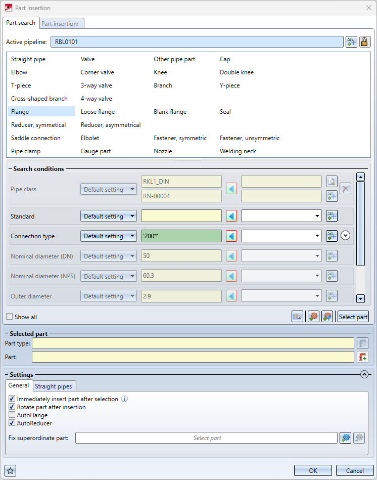
After selecting the part type, the search criteria will be narrowed to those constraints that make sense for the selected part type. With a click in the drawing, the default search criteria (left column) can also be filled in.
For each search condition there are now a number of setting options.
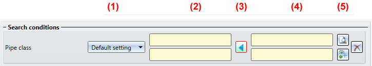
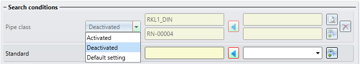
On the far left (1) there is a drop-down menu that controls whether the search condition is evaluated at all during the search.
| Activated |
The search parameter will not be used. |
| Deactivated |
The search parameter will not be used. These parameters are greyed out.
|
|
Default setting |
The search parameter will be used depending on the part type and the Plant Engineering settings for search parameters. |
The next column (2) contains the automatically preset search condition. If you click on a position in the drawing, the entries will be filled accordingly to include the part type at this position.
The next column (3) contains an arrow. This indicates whether the automatically generated  search condition or the one specify by you
  is used.
The column next to the arrow (4) contains the search condition you have specified. Any condition that corresponds to the Plant Engineering search syntax can be entered here. The specification of units is also possible here, e.g.:

Column (5) contains a button  with which you can pick up a search condition from the drawing. The following buttons are also available for pipe classes:
|
|
Activates the pipe class search |
|
|
Deletes the manually entered pipe classes |


Various search attributes are arranged in groups, such as connection types. In this case, you can click to expand the whole group and set it according to your requirements.

There are three buttons under the search conditions.
|
|
Reset user inputs Reset the search conditions you entered. |
|
|
Select reference part Picking a part in the drawing to fit it again. If a pipeline with a pipe class is active, a message is displayed if the pipe class of the selected reference part does not match the pipe class of the pipeline. However, the part can still be selected as a reference part.
This also applies to function Reference part, filter |
|
|
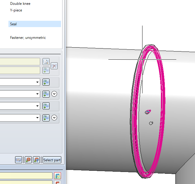
Reference part, filter Allows you to filter the selection by the active part type. This button is only available if a part type is selected at the top of the dialogue. In contrast to the usual selection of a reference part, only a part with the selected part type can be selected.
This selection mode is intended for parts that are difficult to select without narrowing the part type. For example, a gasket may be completely hidden by a fastener. Through the filtered selection, though, it can still be selected. |
|
|
Select part
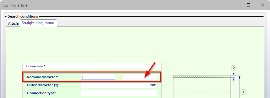
Search for a part. The specified conditions are used and HELiOS or the catalogue is searched for a part to be inserted. The distinction between the nominal diameters DN (for the nominal diameters that correspond approximately to mm) and NPS (for nominal diameters that are applied to inches) is also taken into account in the HELiOS search masks for the part search in Plant Engineering. In the field on the right, which is used to search for the nominal width in inches (NPS), an entry in floating point numbers is expected, e.g. "2 instead of 2". This affects all search masks for parts in which the attribute Nominal diameter is present in this form.
|


 .
. 

Selected part
If a part has been selected successfully, the part type and the part name are shown in the Selected part area.
Highlight similar places / Insert everywhere
A selected place can also be directly inserted in all similar places. This is possible for the following part types:
- Straight pipe,
- Elbow,
- T-piece,
- Knee,
- Branch,
- Flange, and
- Welding neck.
One distinguishes between 2 methods:
|
|
Insert everywhere This option allows you to automatically insert a part in all similar places. If you have not selected a part so far, first define the insertion position of the selected part type, e.g.
Then select the desired part after clicking on Example
|
|
|
Highlight similar places This symbol is only active if you have already selected a part. All possible insertion positions are then displayed for this part, so that you can explicitly trigger the insertion at the desired positions with one click.
A special feature is the insertion of flanges in all places. If no position is individually pre-marked, counterflanges are matched only with identical flanges. However, flanging can also be performed at free ends by preselecting a free end.
|


Part insertion
As soon as a valid part has been selected for insertion, a new tab appears at the top of the dialogue, in this case Part insertion: Standard. While in this tab, a click in the drawing no longer means that the search conditions are modified, but that the part is inserted.
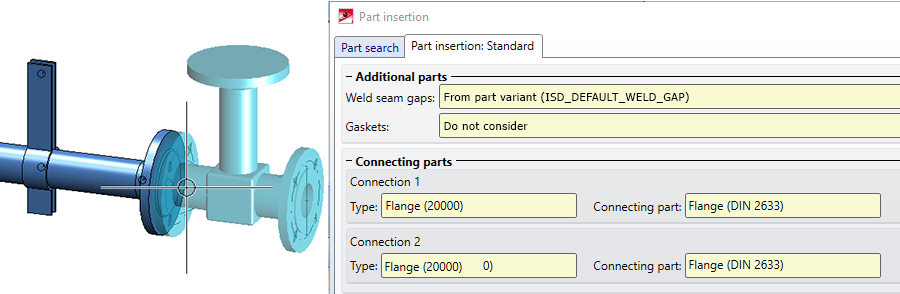
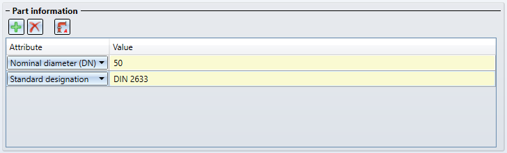
Additional information about the selected part is displayed on this tab, e.g.
|
|
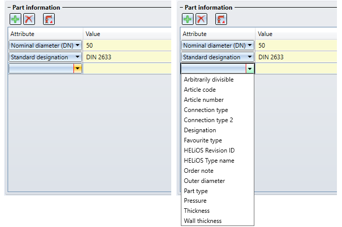
Clicking this button inserts a new row in the attribute list after the current line. Using the selection box of the row, you can then select the attribute to be displayed.
To change the attribute display of a row, simply select the desired attribute in the selection box. |
|
|
A click on this button deletes the current row of the attribute list.. |
|
|
Clicking this button restores the default state of the attribute list.. |


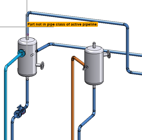
When placing the part, a preview is displayed. A red preview means that the selected place is not suitable for inserting the part.
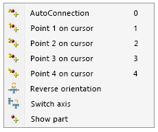
During insertion, an attempt is made to automatically connect a part with the most suitable connection. For example, when connecting a flange to a fitting with a flange connection, the part is automatically rotated so that the flange connections meet. The context menu also contains other settings that can be used to control the insertion, some of which also have shortcuts:
|
|
|
Shortcut |
|---|---|---|
|
AutoConnection |
Automatically tries to determine the best possible connection. |
0 |
|
Point n on cursor |
Switches off the AutoConnection mechanism and inserts the part with the default connection. |
1 - 9, depending on part / connection |
|
Reverse orientation |
Controls the direction in which a part is placed on a guideline. |
|
|
Switch axis |
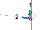
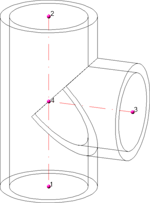
Some parts have "axes" along which they can be placed on guidelines. For example, if you select a cross and have point 5 at the cursor, either the axis from 1 to 2 or the axis from 3 to 4 can be placed on a guideline. This option allows you to change this axis. |
|
|
Show part |
This option for freely positioning the part at an individual point has been added. For this purpose, a preview of the part is displayed where you can select any point.
After selecting the point, the part is attached to the cursor at the corresponding position and can be freely positioned in space. Another option is to select any point and then select an edge for positioning. Then the cursor is attached to the selected point of the part. This is projected onto the edge, so you can align the part to the selected point on the edge.
|
|
In addition, the TAB or SHIFT+TAB key can be used to change to the next or previous connecting point.
A special feature is the insertion of straight pipesand freely placeable parts (e.g. T-pieces or Branches).
Straight pipes
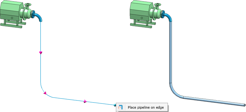
Here you have to select the start and end point between which the pipeline can be routed along. In the meantime you can see a preview of the pipeline route.
When inserting straight pipes, the option Place pipeline on edge is available in the context menu. This function has been extended and now places bent pipelines on bent guidelines:
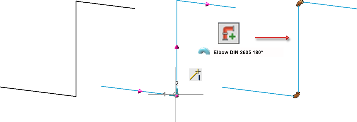
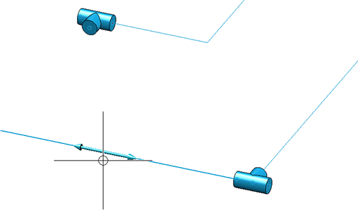
Freely placeable parts
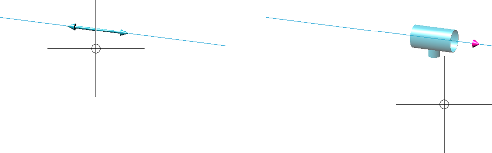
For parts that can be placed freely (e.g. T-pieces or branches), selecting an edge does not directly lead to the part being dropped. When you move the cursor near an edge, a preview is first displayed as follows:
Now you have two options:
- You click on the edge. Then a preview of the part is displayed as usual.

This part can now be flexibly aligned along the edges, for example at other connections. Only when the placement or connection point is selected does the insertion take place.
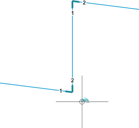
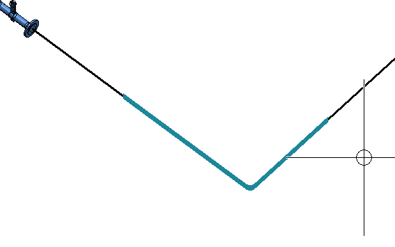
Alignment to other connections is also indicated graphically. If a guideline edge is selected and then another connection, the part will be aligned to that connection. This means that if the part can be rotated around the guideline edge so that the connection of the part and the selected connection are aligned, this rotation is suggested to you. A dashed line shows you that the connections are aligned with each other. 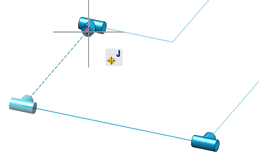
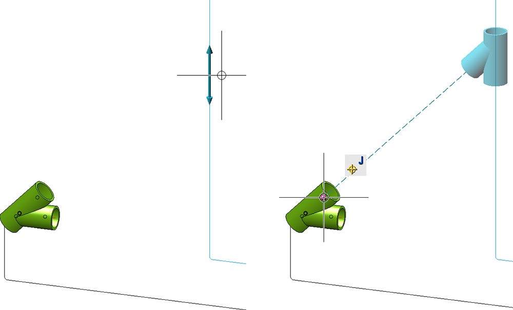
Otherwise, the next point on the guideline edge is used for placement.
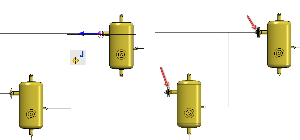
- If the part is to be attached directly to another connection, select the desired connection or point without clicking the guideline edge first. The part will then be placed directly.
![]() Please note:
Please note:
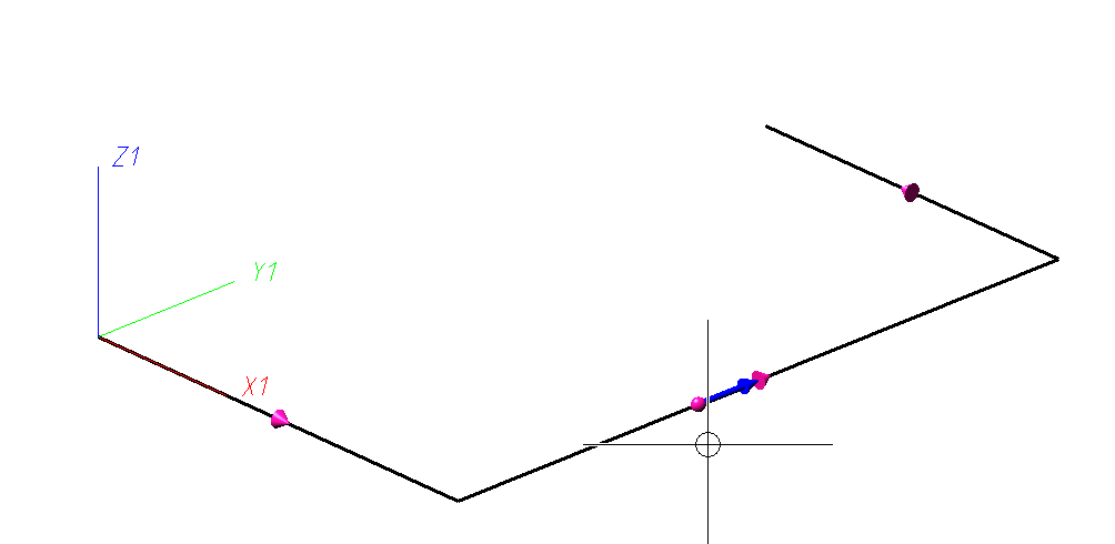
-
If you move the cursor over a guideline, the flow direction is shown. The flow direction arrows are always shown on the guideline over which the mouse has been moved.
- It is normally not allowed to place a pipe clamp freely in space. An exception is when the pipe clamp is installed as a sub-part of a fixed superordinate part. In this case the pipe clamp is not part of a pipeline, so the free placement does not create an invalid pipeline structure.
-
While using the Pipe parts function, the Undo and Redo functions of the transparent toolbar or the quick access toolbar can be used after insertion of a part.
Settings
At the bottom of the dialogue there are various settings on the tabs General and Straight pipes:
General
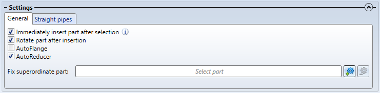
| Immediately insert part after selection |
If you click on a place where the part can be placed unambiguously (e.g. a guideline corner or a part connection), the part can be inserted immediately after the search. This option controls whether this happens. If a part is successfully inserted after the selection, there is no automatic switch to the Part insertion tab. However, you can still insert the part several times by switching manually. |
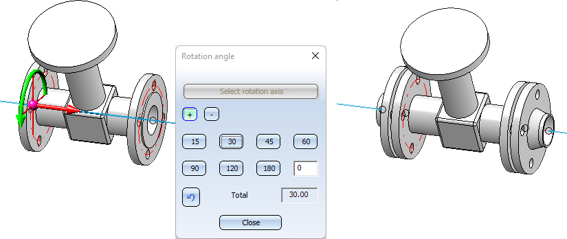
| Rotate part after insertion |
This option controls whether the part rotation dialogue should be displayed after insertion of a part. |
| AutoFlange |
If this option is active, flanges are connected to all flange connections of the inserted part. The option is also available for welding necks. |
| AutoReduce |
If this option is active, a check is made at all connections of the part after installation whether the nominal width matches the nominal width of the pipe or the guideline. If not, an attempt is made to install a corresponding reducer. |
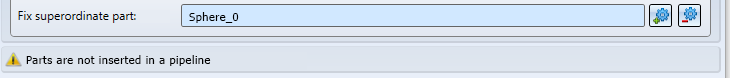
| Fix superordinate part |
This option is only intended for vessel construction and replaces the Plant Engineering settings Insert part as main part/sub-part. When building a vessel, it allows you to select a part under which the new part will be inserted. With this option, no piping can be selected. Also, a warning is displayed if this option is active, as it is really only for container construction and otherwise you will quickly get errors in the body structure.
|
Straight pipes
The fields for inserting straight pipes correspond to those on the Straight pipe tab in the Plant Engineering settings.
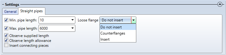
If the checkbox Insert connecting pieces is active here, the connecting pieces specified in the Plant Engineering Settings for straight pipes are automatically inserted when straight pipes are inserted.
If no connecting pieces are preselected in the Plant Engineering Settings, this is indicated by the  symbol in the Part insertion dialogue window.
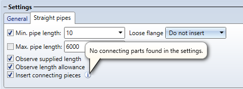
Please note:
Connecting pieces are also inserted if the checkbox in the Plant Engineering settings for straight pipes is deactivated, but activated for part insertion.
Favourites
At the bottom left of the dialogue there is also a button to save Favourites  . All settings as well as values entered by the user are saved and can be reloaded at any time. In this way, a configuration can be compiled for certain subclasses, which will be used again and again in the search.
The Show all checkbox under the search criteria is also provided for this purpose. The search attributes are hidden depending on the currently selected subclass. By activating the checkbox, all can be shown in order to be able to fill in all fields when creating the favourites.
You can find out more about managing favourites here.
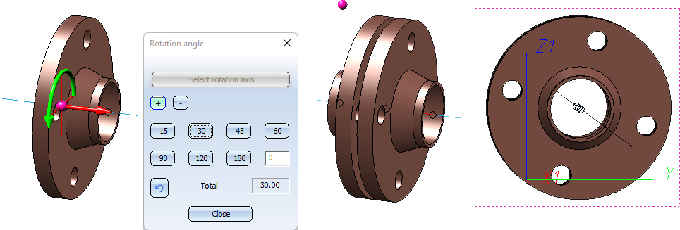
Rotate flange connections
When installing parts with sub-part flanges, e.g. valves, if you rotate the part after insertion, these flanges will now be rotated as well. The same applies if the AutoFlange option is activated.

Pipe Parts (PE) • Part Selection - Catalogue or Database (PE) • Einstellungen: Settings: P+ID Attribute Assignment (PE)