Notes on Part Types

Branch
This part can be branched with a saddle connection or another pipe with a smaller diameter, each in a cylindrical section ending in a connecting surface. Multiple branches (in different directions) can be made from one branching point. In the case of a branch, the branching point may also be located at Point 4. Further information can be found here.
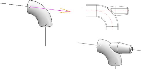
Elbow
When inserting an elbow, the guideline will be processed as follows:
The corner is replaced with an arc edge of matching radius and arc length. This new edge is placed on Layer 0, i.e. it is only visible when this layer is activated. The edges previously converging at the corner are shortened accordingly.
Knee
This part can be branched with with a saddle or another pipe with a smaller diameter, each in a cylindrical section that ends in a connecting surface. Multiple branches (in different directions) can also be made from one branching point. For more information, click here.
Straight pipe
A straight pipe modelled as a feature variant cannot be installed as a "bent pipe".
T-piece
This part can be branched with a saddle conection or another pipe with a smaller diameter, each in a cylindrical section that ends in a connecting surface. Multiple branches (in different directions) can be created from one branching point. The branching point may also be located at Point 4. Further information can be found here.
Flange
- When using self-designed variants for flanges or parts with flanges, please read the notes on bolted flange connections!
- With the options for connecting flanges, the search conditions for the flange to be connected are always based on the flange connection to be connected to. This means that the nominal size agreed for the pipeline or the guideline is always ignored here. This also applies if the Ignore nominal diameter setting has not been set. If the flange connection to which the connection is made belongs to a flange, then exactly the same flange is installed as the matching flange; this also applies if the pipeline is assigned a pipe class that does not contain this flange.
Loose flange / Plane flange
- Loose flanges can be positioned not only when a guideline is placed automatically by the automatism itself, but can also be added manually to a pipeline.
- Plane flanges can also be inserted with projection, i.e. the flange is pushed down from the straight pipe by a fixed predefined value. This value can be defined in the Configuration Editor at Plant engineering > Layout plan with the parameter Insert plane flange, with connection.
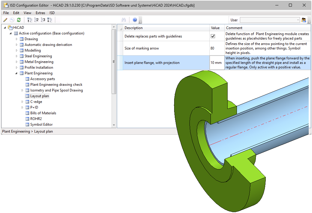
Entering the value 0 or a negative value causes loose flanges to be inserted as usual. If a positive value is entered, then each loose flange is installed like a regular flange. In particular, when connecting to a straight pipe, the second point must be connected instead of the first point as is usual for loose flanges. The default setting is 0.
- A loose flange which is located at a free pipe end can be deleted individually. A loose flange which is connected to another flange connection can only be deleted if the pipe to which the flange belongs is deleted.
Please also read the information in the next paragraph, Welding neck flanges and loose flanges.
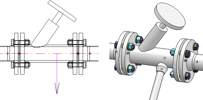
Welding neck flanges and loose flanges
HiCAD supports the insertion of welding neck flanges with loose flanges. Corresponding variants are available in the standard parts inventory for Plant Engineering.

Please note the following:
In pipeline planning, there is the situation that loose flanges can be installed once as flanges and once as connecting elements. This leads to problems, especially in interaction with HELiOS, because in the worst case two articles have to be created for one part, once as a flange and once as a connecting element.
Since HiCAD 2023 SP1, the existing fastener loose flanges are therefore additionally classified as flanges. The context in which these loose flanges were previously used is as fasteners for welding neck flanges. These were previously designed as flanges.
Since HiCAD 2023 SP1, welding neck flanges have been available as a new component type. On the one hand, these are designed to interact with the regular loose flanges. On the other hand, however, they support functionalities that are otherwise found in flanges. One example is automatic setting at free ends and automatic mating flanging.
In the case of welding neck flanges and loose flange handling, a distinction must therefore be made between
- Welding neck flange and loose flange handling before HiCAD 2023 SP1 and
- Welding neck flange and loose flange handling as of HiCAD 2023 SP1.
HiCAD supports both procedures, but we recommend the one as of HiCAD 2023 SP1.
Welding neck flange and loose flange handling before HiCAD 2023 SP1
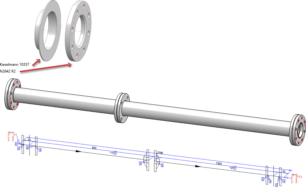
With the variants KM10357_WN_DIN.VAA and ROFI10357_WN_ISO.VAA, the standard part inventory contains two part families that are themselves classified as flanges, but actually represent only welding neck flanges:
|
Variant |
Standard designation |
|
|---|---|---|
|
KM10357_WN_DIN.VAA |
Kieselmann 10357 |
|
|
ROFI10357_WN_ISO.VAA |
RO-FI 10357 |
contains all sub-types of the modelled welding neck flange |
|
ROFI10357_WN_ISO_R1.VAA |
RO-FI 10357 R1 |
contain one portion of the sub-types from ROFI10357_WN_ISO.VAA each |
|
ROFI10357_WN_ISO_R2.VAA |
RO-FI 10357 R2 |
|
The variants refer in their connection type to the loose flanges of the standard DIN 2642, which are classified as asymmetric fasteners:
|
Series |
Variant |
Standard designation |
|---|---|---|
|
1 |
N2642_LF_R1.VAA |
N2642 R1 |
|
2 |
N2642_LF_R2.VAA |
N2642 R2 |
The loose flanges of Series 1 match the variant ROFI10357_WN_ISO_R1.VAA. The loose flanges of Series 2 fit the variants ROFI10357_WN_ISO_R2.VAA and KM10357_WN_DIN.VAA.
There are two ways to model your own flanges:
- Model the flare as a straight pipe
In this mode, the flare is a straight pipe to which regular loose flanges are assigned. This method has disadvantages if an isometry is to be generated from the pipe. Then the flange symbol of the loose flange is slightly offset. - Model the flare as a flange
The flare itself is of the flange type, while the loose flange is an asymmetric connection element. Since the flange symbol is assigned to the flare, the positioning of the flange symbol does not depend on a possible move of the loose flange when generating the isometric drawing.
Welding neck flange and loose flange handling as of HiCAD 2023 SP1
To the parts that were designed to use loose flanges as fasteners before HiCAD 2023 SP1, versions have been added with HiCAD 2023 SP1 that function as a welding neck flange-loose flange combination.
The fastener loose flanges N2642_LF_R1.VAA and N2642_LF_R2.VAA are additionally offered classified as flanges.
|
Series |
Variant * |
Standard designation |
|---|---|---|
|
1 |
N2642_LFC_R1.VAA |
N2642 R1 |
|
2 |
N2642_LFC_R2.VAA |
N2642 R2 |
The part families KM10357_WN_DIN.VAA and ROFI10357_WN_ISO.VAA (previously classified as flanges) are available classified as welding neck flanges:
|
Variant * |
Standard designation |
|
|---|---|---|
|
KM10357_WNC_DIN.VAA |
Kieselmann 10357 |
|
|
ROFI10357_WNC_ISO.VAA |
RO-FI 10357 |
contains all sub-types of the modelled welding neck flange |
|
ROFI10357_WNC_ISO_R1.VAA |
RO-FI 10357 R1 |
contain one portion of the sub-types from ROFI10357_WN_ISO.VAA each |
|
ROFI10357_WNC_ISO_R2.VAA |
RO-FI 10357 R2 |
|
* The C in the file name of the adapted variants stands for collar (as short form of weld neck collar).
The loose flanges of series 1 fit the variant ROFI10357_WNC_ISO_R1.VAA. The loose flanges of series 2 fit the variants ROFI10357_WNC_ISO_R2.VAA and KM10357_WNC_DIN.VAA.
For modelling your own welding neck flanges, please read the information under Part type: Welding neck flange or Variant for part type: Welding neck flange .
Seal
These insertion options take into account the Plant Engineering settings of the Part selection tab, under Flange gasket:
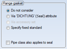
- If a specific gasket standard is specified for the target part in its DICHTUNG (Seal) attribute and the corresponding option is set in the Plant Engineering settings on the Part selection tab, this is used for part search.
- If a specific gasket standard is fixed in the plant engineering settings on the Part selection tab, this is used for the part search.
- If the option Do not consider is activated in the settings, then the gaskets available in the database with a suitable nominal diameter are offered for selection during the interactive insertion of a gasket. If the part search leads to only one part, this part will be used without displaying the results list.
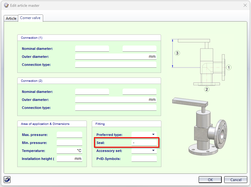
The insertion of gaskets can be prevented via the article master of a corresponding part. To do this, set the attribute value for DICHTUNG (Seal) to the value - (minus) in the article master. This ignores gasket settings at all connections of the part, i.e. no gaskets are set. This also applies when other parts are connected to this part.
Example:
Pipe clamp / multiple pipe clamp
When inserting a pipe clamp (or multiple pipe clamp), a distinction must be made between
- pipe clamps that have the outer diameter attributes D_AUSSEN and D2_AUSSEN and
-
pipe clamps that only have the outer diameter attribute D_AUSSEN.
If both outer diameter attributes are available, then the Also use Outer diameter 2 as search criterion for pipe clamps checkbox must be active in the Plant Engineering settings on the Part search tab.
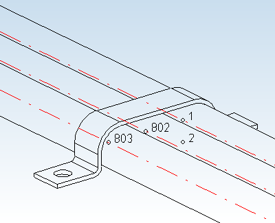
Special named isolated points for multiple pipe clamps
As with all parts of the pipe clamp part type, the insertion reference point for the multiple pipe clamp is the insulated point with the designation 1. After insertion, this point lies on the center axis of the "first" pipe held by the clamp. Other named isolated points specify the location of the center axes for the other pipes that will be fixed with the clamp: 802 for the second pipe, 803 for the third pipe, etc. Point 2 is an auxiliary point needed for the orientation of the clamp during insertion.
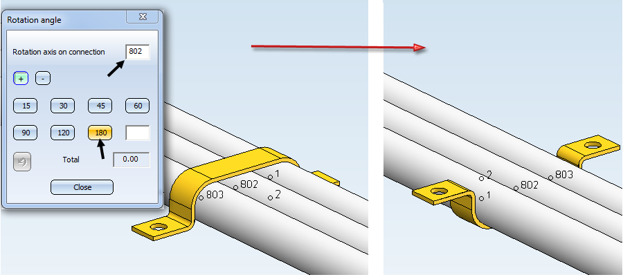
Points 802, 803 etc. can also be used with the Rotate part function:
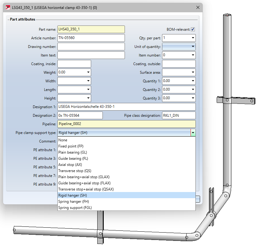
The Pipe clamp support type
The Pipe clamp support type attribute - attribute name PIPE_SUPPORT_TYPE - can be assigned to pipe clamps using the Part attributes function. By assigning this attribute, different pipe support types can be displayed in ROHR2.
In addition, the entries now also show the ROHR2 abbreviations so that you can assign them more easily.
Furthermore, from SP2 it is possible to define support type-dependent symbols to be used for visualisation in an isometric drawing.
If a support type has been assigned to a pipe clamp and a symbol has been assigned to this support type, the original symbolic representation of the pipe clampin the isometric drawing is replaced by the symbol of the support type.
The symbols for the support types can be found in the PlantParts\Symbols\PipeSupport sub-folder.
In the same directory you will find the file support_type_symbols.txt, which makes the assignment between the support types and the symbols. The file uses the abbreviations known from ROHR2 for the support types. A symbol is assigned using a line of the form
Abbreviation="filename without extension"
Example:
FP="fixed_point"
This means that the symbol fixed_point.FGA is assigned to the support type FP.
Reducer
Concentric reducers can be branched with a saddle connection or another pipe of smaller diameter, each in a cylindrical section ending in a connection surface. Multiple branches (in different directions) can also be made from one branching point. Further information can be found here.
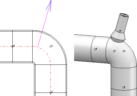
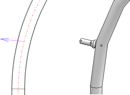
Saddle connection and Elbolet
Parts of the type Saddle connection can be attached to any pipe part (referred to below as the target part). A special case of saddle connections are Elbolets, which can be used as outlets for 90° bends and with which a branch can be realized at an elbow. The elbolet is welded onto the elbow in such a way that its central axis is perpendicular to one of the two connecting surfaces of the elbow and passes through the associated connection point.
The following rules apply to the insertion of saddle connections/elbolets:
- If the target part is a straight pipe, an elbow or a T-piece, then it must lie on a guideline. For Elbolets, only elbows are permitted as target parts.
- If the target part belongs to another part type, it does not necessarily have to lie on a guideline.
- Only Elbolets and no other types of saddle connections can be placed on elbows.
- A saddle connection or Elbolet must always lie on a guideline.
- The guideline on which the saddle connection is to lie must start or end on the centreline of the target part. In the case of the Elbolet, the start or end must lie on connection point 1 or 2 of the pipe bend. For all other saddle connections, the start or end must not be on a connection point of the target part.
![]() Please note:
Please note:
Elbolets according to ASME ANSI standard are available only for certain elbows (ASME ELBOW LR... ). The nominal inch diameter of the Elbolet must match the nominal diameter of the elbow. If no suitable Elbolet can be found for an elbow, a corresponding message will be displayed:
- No matching part found in catalogue. (Data source: Catalogue) or
- No entry in database found for selected Project or Folder. (Data source: Database)

Part Selection - Catalogue or Database (PE) • General Information on Pipe Parts (PE)