Component Connections
Plant Engineering > Part Tools > Exchange  > Component connections
You can use component connections to extend general 3-D parts in such a way that pipelines can be attached to them with the help of the HiCAD module 3-D Plant Engineering.
A component connection consists of a sub-part that contains, as the only graphical object, a named isolated point (the so-called connecting point). Some properties which are to be assigned to this connection are saved with the part in the form of Plant Engineering attributes. These are:
- Connection type
- Pipe class
- Nominal diameter
Pipe class and Nominal diameter can later be applied to the pipeline to be connected. When allocating parts to guidelines automatically, the Connection type determines, amongst other things, the permissible part types (flange or pipe) for the part to be attached to the connecting point.
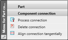
The following functions are available:
|
|
|
|
|
|
|
|
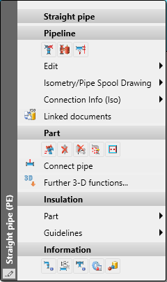
In the context menu of component connections you can also find the function Align connection tangentially  .
.

Insert component connection
Plant Engineering > Part Tools > Exchange > Insert component connection 
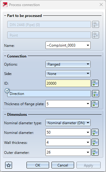
After calling up the function, the dialogue window shown is displayed:
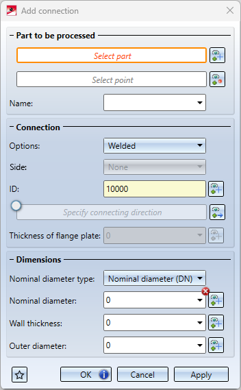
First select the part that is to receive the connection.
Then the selection of a point is started automatically. Select the desired point in the drawing. This point determines the coordinates of the connection.
If you want to change the selection of the part to be processed or the point again, click on the  or the
  symbol.
Then define the attributes of the component connection:
|
Name |
Determines the name of the sub-part. You can accept the name suggested by HiCAD or enter a different name.. |
|
Connection |
|
|
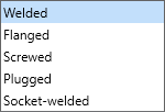
Options |
Select the desired connection type from the listbox.
|
|
Side |
Here you determine the connection side.
|
|
ID |
The identifier (ID) is entered automatically. However, it can be changed by picking a part in the drawing. To do this, click on |
| Connecting direction |
The specification of the connection direction is optional and can be activated / deactivated if required by clicking on |
| Thickness of flange plate |
This value can only be specified if Flanged has been selected as the connection type. With a click on |
| Dimensions | |
| Nominal diameter type |
Select the nominal diameter type DN or NPS. |
| Nominal diameter |
The nominal diameter must be specified. The component connection will not be created without specifying the nominal diameter! |
| Wall thickness |
Enter the desired values or click on |
| Outer diameter | |
 or
or  .
.
Buttons
|
|
The settings of the dialogue can be saved as favourites and reused at any time. To do this, click on the |
|
OK |
The selected component connection is created with the current data and the dialogue is closed. If the data is not sufficient for creation or if it is incorrect, this is indicated by a
|
|
Cancel |
Closes the dialogue window without creating the component connection. |
|
Apply |
The component connection is created and the previously selected point is deselected. You can now directly select a new point and create another component connection under the selected part or select a new part after clicking on |

 symbol on the
  symbol. If you point with the cursor to one of the symbols, further information is displayed, e.g.
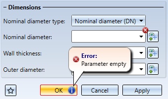
Process component connection
Plant Engineering > Part Tools > Exchange > Process component connection 
To process a component connection, identify the desired connection after calling up the function. The dialogue window shown is then displayed.
Part and point are fixed here, all other parameters can be changed. Click on OK to apply the changes and close the dialogue.
Alternatively, the function is also available in the context menu for component connections.
Delete component connection
Plant Engineering > Part Tools > Exchange > Delete component connection 
Use this function to remove part connections.
Identify the required connection. The associated sub-part will be deleted.
Align connection tangentially
RMB > Align connection tangentially
This function is required for eccentrically inserted pipes and can be chosen from the context menu for component connections.
Straight pipes can be inserted into other parts of the type straight pipe, pipe bend, elbow, T-piece, branch and symmetrical reduction. The end point of the straight pipe does not necessarily have to end on the centre line of the other part, but can be any point.
The prerequisite, however, is that a connecting point is added to the part into which the pipe is to be inserted, which can then act as the end point of the inserted pipe.
Common applications are top-of-pipe or bottom-of-pipe insertion. In both cases, the inserted pipe leads tangentially out of the larger pipe:
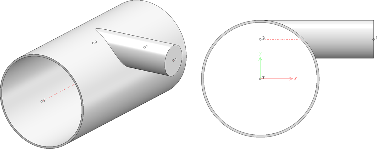
When setting the connecting point freely, it is rather cumbersome to enter this point correctly manually. For this purpose, the outer diameter and wall thickness of the thicker pipe as well as the outer diameter of the pipe to be inserted must be coordinated with each other. This is where the function Align connection tangentially becomes important.
Detailed information including an example can be found in the section Eccentrically inserted pipes.
![]() Please note:
Please note:
Component connections are sometimes difficult to identify, especially in model drawings with many parts. To facilitate the use of this function, the function is also available in the context menu of pipe parts. This way, selection is possible even if the component connection is hidden by other parts.