3-D - What's New?

Service Pack 2 2022 (V 2702)
Views - Show/Hide parts
New in the context menu for 3-D parts and part lists is the Show part list in view selection, hide all other parts  function. This function shows only the active part or - in case of a multiple selection - all selected parts. All other parts will be hidden. This applies to all currently selected views.
Tip:
To subsequently show all parts of the drawing again, select all parts in the ICN with CTRL+A and then select this function again or select the Show part list in view selection  function.
Divide surface
The Divide surface  function has been revised and extended once again.
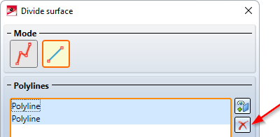
- To remove selected surfaces or lines, a button is now available in the dialogue window.
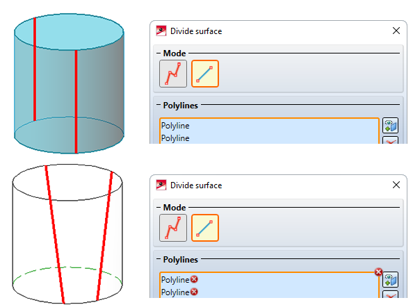
- As of SP2, dividing in polyline mode is also possible if multiple lines converge at one point. However, the lines must not intersect. For more complex divisions in a plane, sketch mode is recommended.
- Freeform curves can also be used for divisions.
- The error texts have been revised.
- To divide whole cylinders or cone surfaces in polyline mode, at least two lines are required. These must divide the surface into at least two new surfaces.
- In sketch mode, surfaces from sectional and detail views as well as cut-outs or sheet developments are not permitted. In polyline mode, this applies analogously to lines.
- In polyline mode, the Perpendicular Point F point option of the Autopilot is no longer supported when selecting the first point of a polyline.
Sketch Technology
Close polyline
The context menu that is displayed while drawing polylines after pressing the right mouse button has been extended by the Close polyline  function.
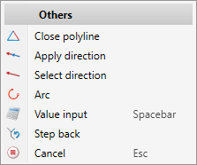
This function closes the current polyline, i.e. the last point will be connected to the start point of the polyline by a new line. The sketching tool will remain active afterwards, so that you can directly draw the start point of another polyline.
Marking of the current drawing plane in 3-D sketches
As of SP2, when working with 3-D sketches, the current drawing plane is displayed in a lighter colour during sketching.
Drawing of tangents
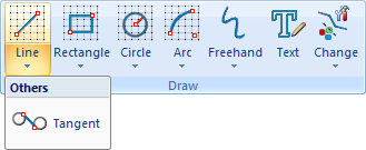
The functions
- Tangent between 2 lines and
- Tangent to surface
have been combined into the new Tangent  function .
- Points, lines and surfaces can be selected for the start and end of the tangent.
- A dynamic preview of the tangent is displayed and the selected start point is visualised.
- The tangent that comes closest to the click points for start / end is always selected. There is no additional query and for tangents to a surface the determination of additional points is omitted.
- For point determination, the point options of the Autopilot settings toolbar can be used - including the Online point O point option.
- If not set otherwise, HCM constraints are automatically assigned. These can be suppressed during drawing by holding down the SHIFT key.
- By right-clicking, a context menu can be activated analogously to other sketch functions.
Optimisation of value input (space bar) when drawing sketches
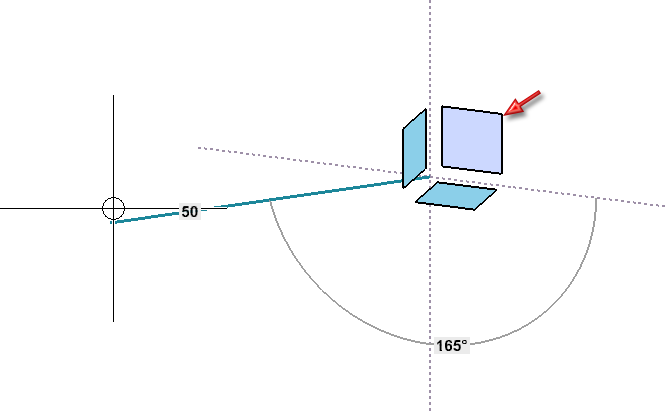
If you want to enter a value, e.g. a length or a radius, explicitly via the keyboard when drawing graphical elements, you can select the Value input  function in the context menu or alternatively simply press the space bar. HiCAD will then display the calculator and you can enter the desired value. As of SP2, the distance and angle to the last point or the X and Y distance to the last point can be entered in one step. The two values must be separated by a space.
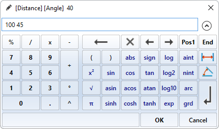
Which entries are possible depends on the respective function and the mode selected there.
|
Function |
Distance + Angle |
XY-grid |
Free |
On axes |
|---|---|---|---|---|
| Line |
Distance Angle |
X distance Y distance |
X distance Y distance |
Length |
| Rectangle |
- |
X distance Y distance |
X distance Y distance |
- |
| Circle |
- |
Radius |
Radius |
- |
| Arc |
- |
Radius |
Radius |
- |
These possibilities do not apply to the start point.
Transition from arcs
The Transition from arcs  function has been revised. Overview of the new features:
- After selecting the start point, the direction in which the arc will be drawn is visualised by an arrow.
- As soon as you move the cursor near a line afterwards, the possible arc will be displayed as a dynamic preview.
- If not set otherwise, HCM constraints are automatically assigned, which can be suppressed by holding down the SHIFT key - as with other sketch functions.
- As with the other sketch functions, a context menu can be activated by right-clicking before a point is applied.
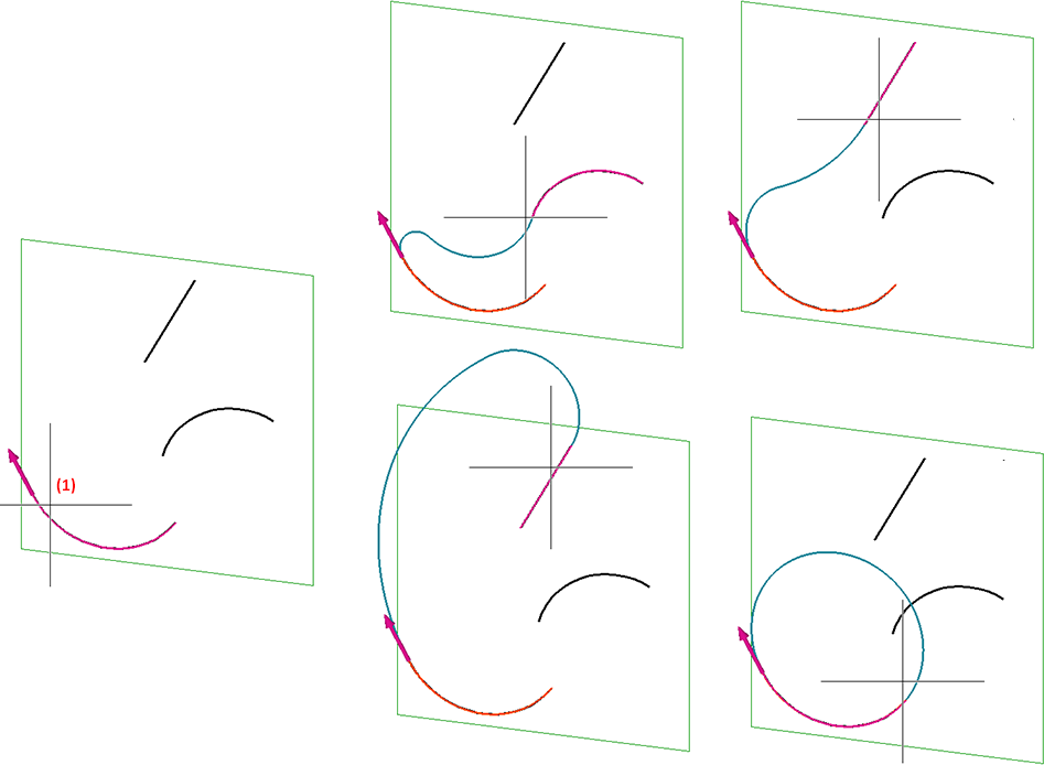
Example
The illustration shows the selected start point on the left and a selection of possible transitions on the right.
Weld seams and symbols
Clone weld symbol
New in the pull-down menu of the 3-D Dimensioning + Text > Symbols > Weld function is the Clone weld symbol  function.
This function allows you to copy existing weld symbols in the drawing and to assign copies to other weld seams. The function is also available in the context menu for weld seams.
Please note that the function will only clone the representation of the weld symbol. The content of the symbol will be read from the selected weld seam line.
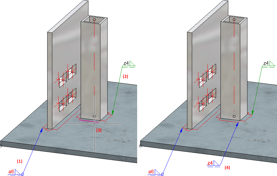
Example:
The illustration shows a free weld seam symbol (1) and a labelled weld seam(2). The weld symbol (1) is cloned and repeated and selected as the weld seam line (3). (4) shows the result.
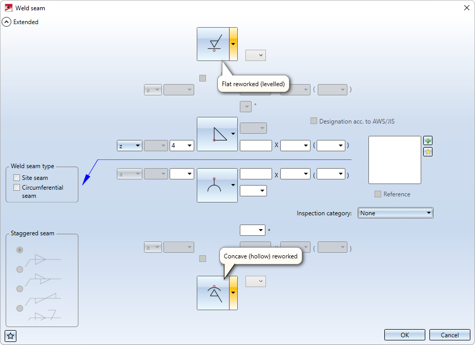
Tooltips for additional symbols
As of SP2, tooltips are also displayed for additional symbols in the dialogues for weld seams and weld symbols.
Text - Itemise part
The Itemise part  function has been extended. The Part selection area is now additionally available here.
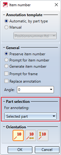
There you have the option of selecting whether the selected part is to be annotated (as previously) or only the 1st sub-part-level. If the 1st sub-part level option is active, then the highest superordinate part of the 1st sub-part level that is BOM-relevant will automatically be searched for and annotated, starting from the selected part. This can be particularly useful in complex drawings if only the assemblies are to be annotated.
Example:
We consider the illustrated drawing.
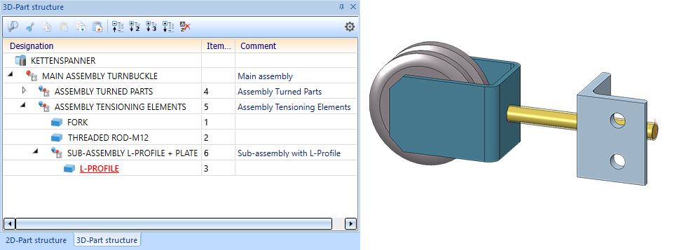
Now the Itemise part function is called, the option 1st sub-part level is activated and the L-profile (1) is selected. In this case, the highest superordinate and BOM-relevant part is the Assembly Tensioning Elements, which is highlighted in colour by HiCAD. This assembly will then be annotated.
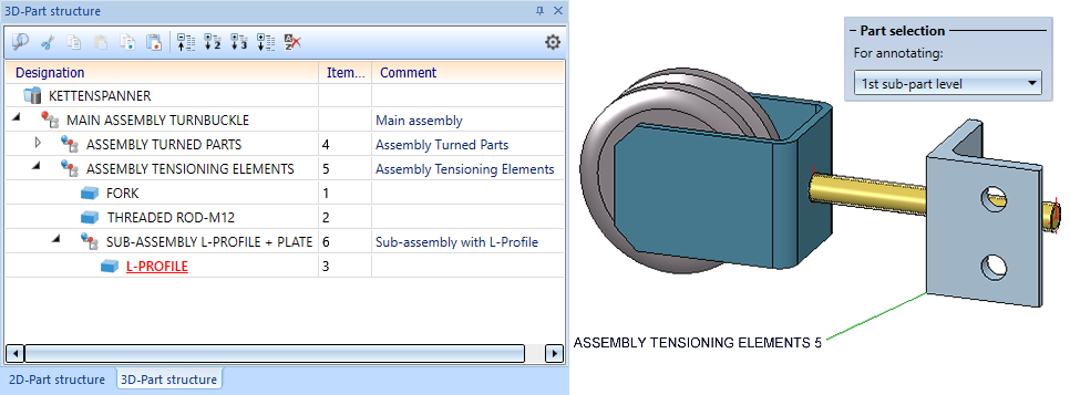
If the function had been executed with the Selected part option, the L-profile would have been annotated instead.
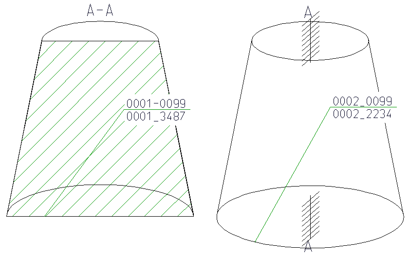
Hatching in section and cut-out
The Hatch section + cut-out function has been completely revised. It affects the active view and allows a preview of the changed hatching. Also new is that a distinction is now made between "normal" hatchings and insulation hatchings.
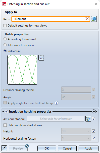
Please note that for certain hatchings no or only a schematic preview can be displayed.
Service Pack 1 2022 (V 2701)
Views
New dialogue when creating new views
The previous functions
 Views > New > Standard
 Views > New > New list view, Select parts
 Views > New > New list view, Copy from another view and
 Views > New > New list view, Copy from active part list
have been combined into the function New view, without link with a new dialogue.
The new function is clearer, offers better user guidance and enables list views to be defined much more quickly.
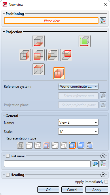
In addition, the representation type of the view, the view name and the scale can now also be selected directly. It is also possible to assign view captions.
Changed meaning of the term "view list"
As of HiCAD 2022 SP1, the term "view list"stands for a multiple selection of views - in analogy to part lists.
The previous use of the term meaning "list of parts displayed in a view" has been replaced by part list of the view or part list for short.
Highlighting of view lists
If a view list is available, i.e. if multiple views are selected, then all selected sheet views will be highlighted by a coloured, wider and dashed view frame. The frame representation corresponds to the settings selected for the active sheet view in the Configuration Editor - but dashed.
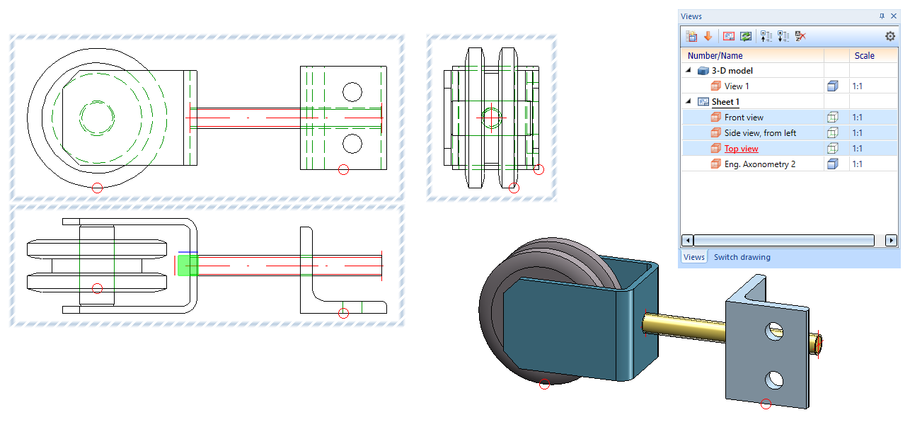
Automatic assignment of numbers as view designation
Up to now only capital letters were automatically assigned in view markings, i.e. the smallest letter not yet assigned was suggested as a designation (detail views start with Z and run backwards in the alphabet). If, for example, the drawing contained sectional views with the designations A and B, then designation C was automatically suggested for the next sectional view and so on. If the drawing contained sectional views with the designations A and C, then the next letter not yet assigned was searched for, i.e. B.
As of HiCAD 2022 SP1, this behaviour also applies to the use of numbers in view markings. This means that, when creating a new sectional or detail view or for view markings according to the arrow method, the smallest number not yet used will be searched for in the view dialogues of the corresponding functions and suggested as a designation. Views that only have a caption (without a designation in an original view) are also taken into account.
Whether a letter or a number is suggested depends on the last designation used. For example, after a sectional view with the designation A, a letter will be used again for the next sectional view, and after a sectional view with the designation 1, a number will be suggested again.
Views window of the ICN - Changed column headers
Due to the risk of confusion between the column header Designationin the Views window of the ICN and the term Designation(view designation, section designation, detail designation) in different view dialogues, the column header Designation in the ICN has been changed to Number/Name.
Show/Hide isolated points in view
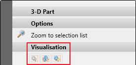
Analogously to assembly points, isolated points can now also be shown/hidden in views. The Show/Hide elements in view  function has been extended accordingly.
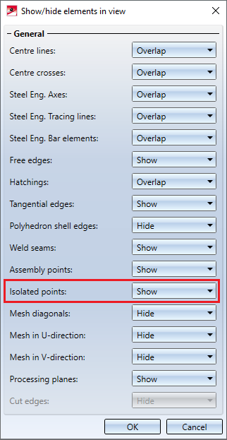
Isolated points also include named points, symbol points and fitting points.
Please note that isolated points can be hidden globally by means of the Drawing > Others > Visual... function. If you have hidden isolated points in this way, they cannot be shown again with the Show/Hide elements in view function.
![]() Please note:
Please note:
- The function only affects the currently active view. Multiple selection of views is not possible.
- For assembly points and isolated points, hiding always affects only the existing points. This means that if further isolated points or assembly points are created, these will be visible. You must first recalculate the view in which the isolated points and assembly points are already set to Hide. To do this, use the functions found under Recalculate views in the context menu of the Redraw function.
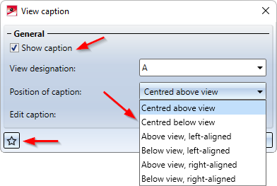
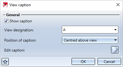
Improvements for view captions
- The function View caption has been renamed to Create/edit/delete view caption(s).
- The settings of the View caption dialogue window can now be saved as favourites. In order to do this, click on the
 symbol at the bottom left of the dialogue window. You can find more information on managing favourites under Favourites in the HiCAD Basics.
 - The checkbox View caption has been renamed to Show caption.
- View captions can now be aligned above or below the view, not only centred but also left-aligned and right-aligned. The alignment refers to the geometry displayed in the view (without annotations).
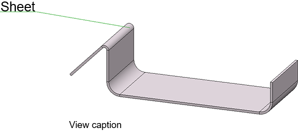
Below view, left-aligned
- As of SP1, the alignment can no longer be changed in the context menu for view captions.
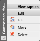
-
To edit a view caption, it is now also sufficient to double-click on the caption to display the View caption dialogue window.
- If the active view is a sectional or detail view or a view marked according to the arrow method, the View caption field in the View designation dialogue window is locked and greyed out.
Sketches
Extended range of points on the Autopilot
When sketching planar sketches and 3-D sketches, in addition to the points in the sketch, the point options X and Y are now also offered for the last point found by the Autopilot (with the exception of the point option O). This does not happen directly when you "run over" a point, but only when you briefly stay on this point with the mouse. This point will then be visualised graphically.
Example:
You move the mouse over the middle of a line. Then the Autopilot will offer the point option Midpoint. However, you do not click but move the mouse further after a short moment. The midpoint will be visualised graphically and from now on the Autopilot will offer the point options X and Y for the coordinates of the midpoint.
As of HiCAD 2022 SP1, this option is also available when inserting isolated points in a sketch.
3-D sketches - New option: Do not leave drawing plane
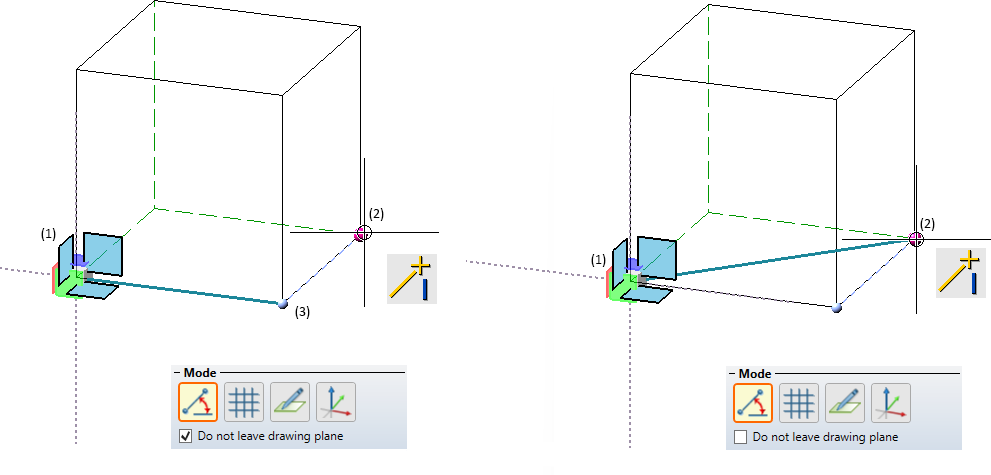
For 3-D sketches, the checkbox Do not leave drawing plane is also available in the Angle+Distance grid, XY - grid and Free modes. Activating the checkbox causes selected points outside of the current drawing plane to be projected onto this plane and thus to be drawn in a plane. For the On axes mode, the checkbox Do not leave axis is available, working in the same way.
Example:
The start point of the line is point (1). Point (2) is selected as the following point. If the checkbox is inactive, (2) will be the determined point. If the checkbox is active, point (3) will automatically be determined.
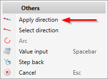
Apply direction
As of HiCAD 2022 SP1, the Apply direction  function is also available in the context menu of the Sketching Tool. With this function the direction of the line shown in the preview is taken over as the direction for the next line to be drawn.
Annotations
3-D annotation with interruption of lines and hatchings
You can set whether the lines of parts and hatchings behind a 3-D annotation should be interrupted under System settings > Annotations > Part annotation in the Configuration Editor. If the option Interrupt background lines is active, hatchings and lines will be hidden. This applies to the representations Glass Model, HiddenLine, HiddenLine dashed and Shaded with Hidden Line.
Please note that this option is read in when HiCAD is started and is active by default. Changes will only take effect after a restart.
Point option O when setting annotations
When determining the reference point of a 3-D annotation, the point option O (online to edge through point) is now automatically activated in the Autopilot settings toolbar. This also applies to the setting of surface symbols.

This applies to the following functions:
Dimensioning
Unit of measurement
In the settings for the parameters for dimensions, the designations for inches (am.) and " (brit.) have been replaced by ft in and ' " respectively.
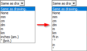
Newly available for selection are in and ". This means that it is now also possible to output values larger than 12 inches completely in inches. Previously, the output was a combination of feet and inches.
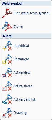
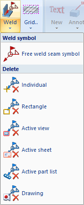
Delete weld seam symbols
There are new functions for deleting weld symbols under 3-D Dimensioning+Text > Symbols > Weld.
Process parts
Divide surface
The dividing of surfaces has been modernised in HiCAD 2022 SP1. The previous function Insert edges in surface / Divide surface (under 3-D Standard > Tools > Edge) has been replaced by the new function Divide surface . You can find the new function under 3-D Standard > Tools > Surface.
With this function you divide surfaces of the active part. For example, the side of a sheet can be divided into two surfaces that can be addressed separately and thus can also be coated, coloured or hatched differently.
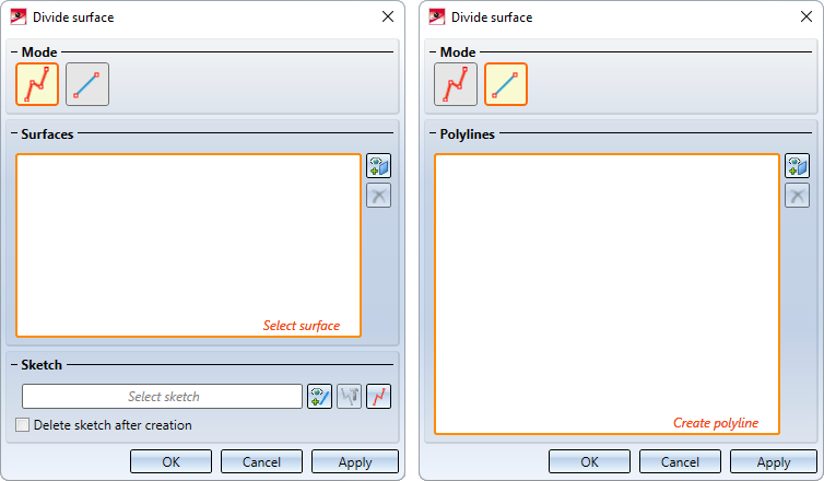
Two modes are available for dividing surfaces.
 Use sketch for dividing
In this mode a sketch is used for dividing. The lines are drawn out internally in the Z-direction of the sketch to form surfaces and are intersected with the surfaces to be divided. Each intersection curve that is closed or goes from edge to edge splits the surface into two pieces. Lines ending in a surface are extended there to enable dividing.
 Use polyline for dividing.
In this mode, instead of a sketch, polylines consisting of straight lines one at a time are used for dividing. These lines must lie exactly on the surface that is to be divided. As a result the surface will automatically be specified and does not have to be explicitly selected. Due to the constraints, only flat, cylindrical and conical surfaces are allowed; the division of freeform surfaces is not possible in this mode.
In the following example, the part (1) was divided via the sketch. After calling the function, the option Tangentially connected surfaces was selected, then the surface (2) and the sketch (3) were selected. (4) shows the result.
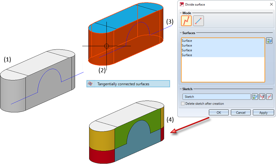
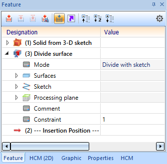
A feature with the name Divide surface is created for each division. Double-click on the entry in the feature log to start the Divide surface function dialogue, for example to process the sketch on which the division is based, to change the surface selection or to select a different polyline.
Clean up intersections
The Clean up intersections  function has been completely revised/modernised and is now identical to the function of the same name under Sheet Metal > Further functions > Extras.
The main improvements:
- extended possibilities, analogous to the clean-up of sheet metal parts,
- improved treatment of multi-part sheets,
- improvement of the automatic selection of the surfaces to be processed,
- consideration of external references and
- simultaneous processing of multiple collision parts.
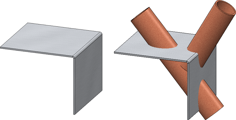
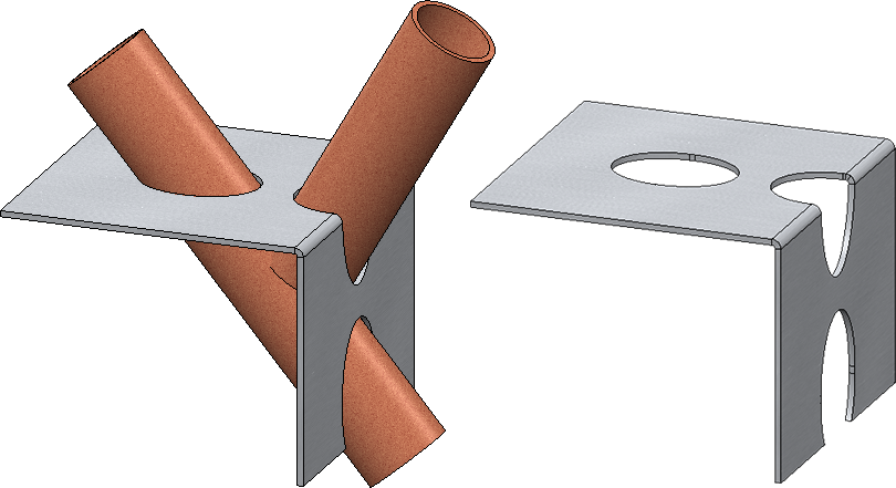
Example:
The pictured sheet metal part colliding with two cylinders should be cleaned up.
The processing should be perpendicular to the surface and all surfaces on the sheet should be processed. Therefore, the automatic surface selection is selected.
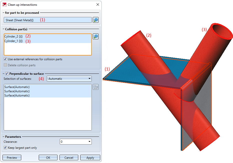
The result:
Major Release 2022 (V 2700)
Sketches
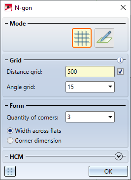
N-gon
The previous N-gon function has been revised. The new N-Gon  function now also uses the sketching tool.
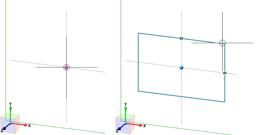
Rectangle with centre point
Sketch > Draw > Rectangle > With centre point
With the new Rectangle with centre point function you draw a rectangle by selecting the centre point and dragging the rectangle. The Sketching Tool is started for this purpose.
Point option O for circles and arcs
With the new sketching functions in HiCAD 2021 SP1, the point option O was previously not available on Autopilot if, instead of a point, a line could also be selected, for example a tangent line to a circle. This behaviour has changed when sketching circles and arcs in HiCAD 2022 in the following way:
- The point option O is also available in the case of a tangential line also being selectable instead of a point.
-
If the point option O is set to determine the centre of a circle or arc or the start point of an arc, then the coincidence constraint is set on the underlying line. If the point is on either the circle or the arc, no coincidence constraint will be set.
Example:
In the illustrated example, an arc is drawn using the Arc  function. For the centre, start and end points of the arc, the point option O is used.
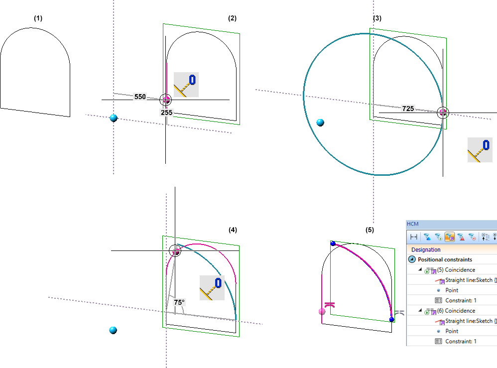
(1) Original sketch, (2) Arc centre point, (3) Arc start point, (4) Arc end point, (5) Outcome with coincidence constraints
Create and process parts
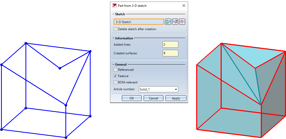
New part from 3-D sketch
As of HiCAD 2022, the algorithm of the New part from 3-D sketch  function has been improved. These improvements have weakened the requirements for the 3-D sketch:
- The sketch may only contain straight lines, curves are not allowed. Auxiliary geometry is allowed but will be ignored.
- The lines of the sketch must not intersect or coincide (lie on top of each other).
- The sketch must consist of lines that are supposed to become edges of the solid to be created. Ideally, all edges should be included as lines in the sketch.
- At least two lines must converge at each line end. If this is not the case, the lines are evaluated as errors and visualised accordingly in the graphic. This way, even small gaps in the sketch can be found quickly.
If the lines of a 3-D sketch are not sufficient to create a solid, HiCAD will - if possible - automatically insert the missing body edges. In the preview, these edges are visualised in the same colour as the resulting part. The number of lines added and of surfaces created are now displayed in the dialogue.
The edges automatically added by HiCAD cannot be influenced. If they do not correspond to the desired result, you must add the missing lines to the sketch.
Error messages will only be displayed in the dialogue directly after calling the function if the 3-D sketch does not meet the requirements and it was not possible to create a useful solid, even by adding lines.
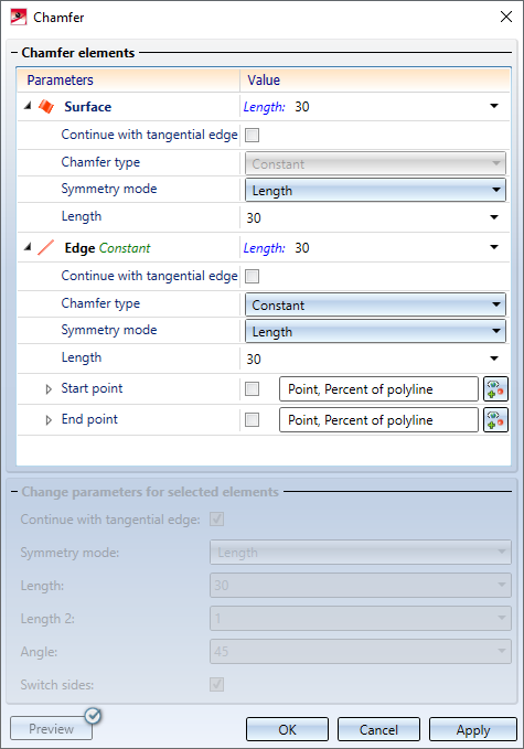
Chamfer
The dialogue of the Chamfer  function has been redesigned - with a wider selection of chamfer elements, improved preview and modification of parameters, extended value input and much more.
New and enhanced options:
- In addition to the selection of individual edges and surfaces, additional elements can now be selected for chamfering via a context menu.
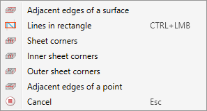
- The previous Chamfer point with adjacent edges function has been omitted. Instead, you use the Adjacent edges of a point function shown in the context menu above.
- Chamfering corners is no longer done via the Chamfer function but via the independent Chamfer corner
 function.
- For edges, the direction of the edge is visualised. This depends on the cursor position when selecting the edge.
- For variable chamfering, intermediate points can be specified as either a percentage of the length of the edge to be chamfered or as a point option. Points that are determined via a point option do not have to be located on the c-edge. They will be projected automatically.
- Segments of edges can also be chamfered - both constantly and variably. The start and end points of a segment can - just like the intermediate points in variable chamfering - be specified as a percentage or as a point option.
- The preview has been improved and can now be updated either automatically or alternatively by clicking.
- When changing parameters of already selected chamfer elements, multiple selection is possible.
- In theElement snapmode, the chamfering function is now also available in the context menu for edges and surfaces.
- As long as you do not exit the dialogue window by clicking the OK or Cancel button, you will be able to chamfer more elements.
- The value input in the dialogue window can contain variables and formulas. In addition, a context menu with further input options can be called by right-clicking. For example, values can also be picked in the drawing.
- The function can also be used via the HiCAD API.
- Chamfered edges and surfaces of a part can be edited subsequently via the Chamfer feature.
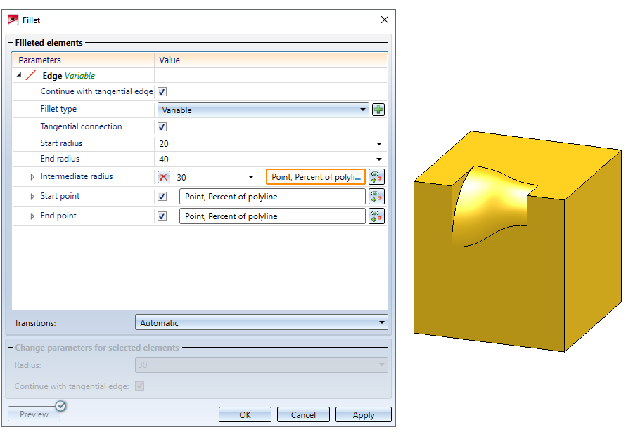
Fillet
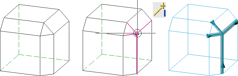
- When filleting, it is now also possible to select all edges adjacent to a point in one step. For this purpose, the context menu for the selection of elements to be filleted has been extended by the function Adjacent edges of a point.
- Filleting of segments is now also possible via variable filleting. Please note that the start point (in relation to the direction) must be located in front of the end point.
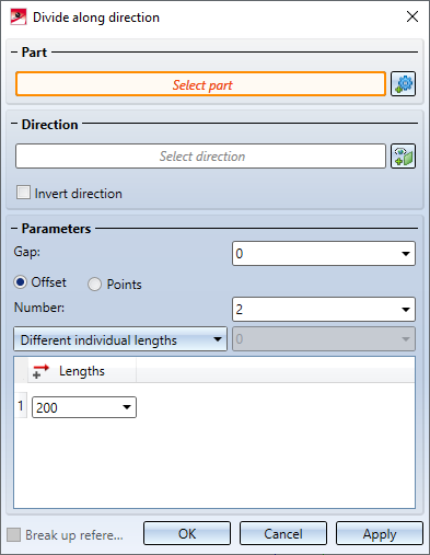
Divide along direction
The Divide along direction  function has been extended.
-
Part selection has been newly added to the dialogue window. The system will always choose the active part for processing, with the name being displayed under Part. If the function is called while an invalid part is active (e.g. a dummy part), the text Select part will be displayed instead of the part name. In this case, you can select the part to be processed directly in the ICN or in the drawing.
If you want to process a part other than the one displayed, click on the
 symbol and select the desired part in the ICN or in the drawing.
- Another new addition is the Apply button. You can execute the division by pressing this button. However, in contrast to OK, the dialogue window remains active and thus further parts can be processed.
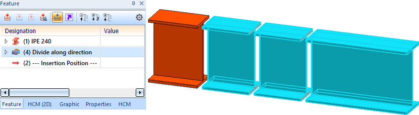
- The preview has been improved. In addition to the direction, the division points and the gap, the resulting segments are now also immediately visualised in the drawing. This also applies to the Divide along direction function in steel engineering.
- If the main feature is selected in the ICN, in addition to the original part, all associated segments in the drawing are now also highlighted in colour. This also applies vice versa. Analogously, this applies to the steel engineering function Divide along direction.
- If the main feature Divide along direction is activated / deactivated, the associated features from division are also automatically activated / deactivated. At the same time the dependent parts will be recalculated accordingly, i.e.:
- If the main feature is deactivated, the original part will be restored and the segments will become dummy parts.
- If the main feature is activated, all segments will be restored.
This also applies to the Divide along direction function in steel engineering.
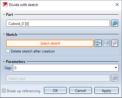
Divide with sketch
The Divide function has been renamed to Divide with sketch  and extended.
-
Part selection has been newly added to the dialogue window. The system will always choose the active part for processing, with the name being displayed under Part. If the function is called while an invalid part is active (e.g. a dummy part), the text Select part will be displayed instead of the part name. In this case, you can select the part to be processed directly in the ICN or in the drawing. If you want to process a part other than the one displayed, click on the
symbol and select the desired part in the ICN or in the drawing.
- The sketch can be deleted automatically after the division.
- If the main feature is selected in the ICN, in addition to the original part, all associated segments in the drawing are now also highlighted in colour. This also applies vice versa.
- If the main feature Divide along direction is activated / deactivated, the associated features from division are also automatically activated / deactivated. At the same time the dependent parts will be recalculated accordingly, i.e.:
- If the main feature is deactivated, the original part will be restored and the segments will become dummy parts.
- If the main feature is activated, all segments will be restored.
- If a sketch has HCM dimensions, they are transferred to the feature as parametric dimensions. If a parametric dimension is changed in the graphics window, this change will adjust the associated HCM dimension.
Limiting angle for shading
In previous HiCAD versions, the Limiting angle for shading function ensured that non-tangential transitions appeared rounded in the shaded view. This function is no longer needed and thus has been removed. This applies to both the drawing properties and the properties of 3-D parts.
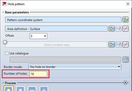
Number of holes in a hole pattern
When using the Hole pattern function, the dialogue window now directly shows how many holes would be created based on the configured hole pattern. Partially created holes (e.g. holes that are located at the edge of the processed area) will be counted as entire holes here. This value is also displayed in the Feature of the hole pattern.
Dimensioning
Snapping of HCM and parametric dimensions
Thus far, when the cursor was pointing to the dimension figure of an HCM or a parametric dimension, the system preferably snapped the geometry behind it. In HiCAD 2022, this behaviour has changed. As of now, HCM and parametric dimensions are preferred.
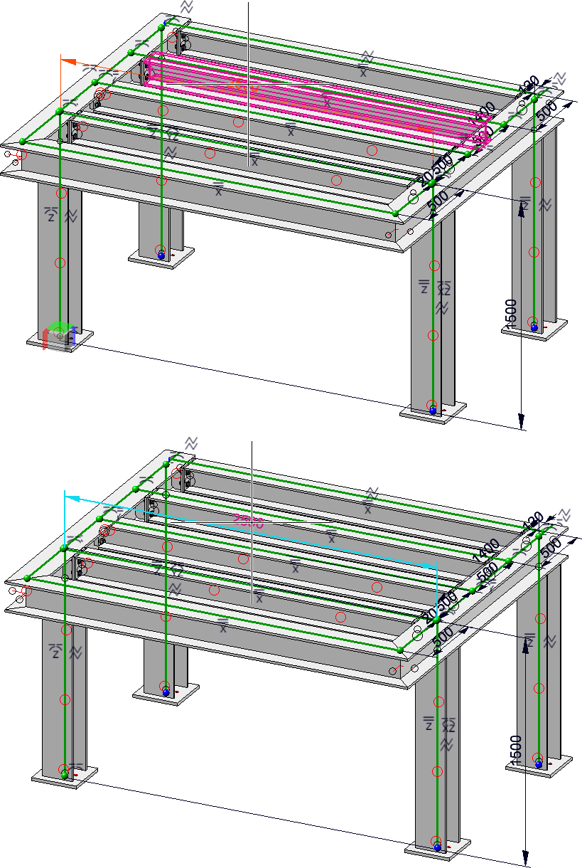
Top: before HiCAD 2022; Bottom: since HiCAD 2022
Renaming of the function group Surface/Edge
The function group Surface/Edge has been renamed to Symbols and moved within the 3-D Dimensioning + Text ribbon.
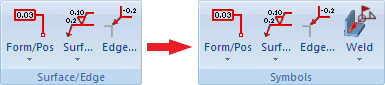
A new feature is that the functions
are also available here.
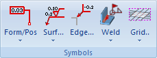
Grid annotation
As of HiCAD 2022, the functions for Grid annotations can be found under 3-D Dimensioning + Text > Symbols > Grid....
Annotations
New file format
With HiCAD 2022, the internal data format of annotations has changed. During the creation of new annotations (also in drawing derivations and sheet developments), the new format is always used. Visually, there are no differences to the "old" format. When loading a drawing that contains annotations created before HiCAD 2022, the following message appears: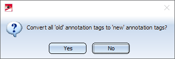
If you click on Yes, the previous annotation tags will automatically be converted to the new format. A message is then displayed, indicating whether or not all annotation tags could be converted, e.g.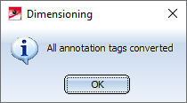
In the ISD Configuration Editor, under Compatibility > Annotations > Part annotation, 3-D, you can preset how to proceed when drawings with "old" annotation tags are loaded and whether a message should be output after a conversion.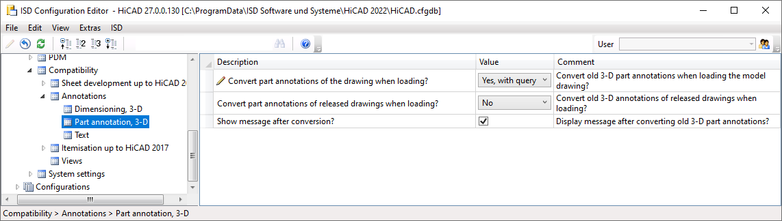
The conversion of old annotation tags can also be done automatically by setting the Convert part annotations of the drawing when loading? parameter to Yes, without query.
Changed context menu
The context menu for part annotations has been changed.
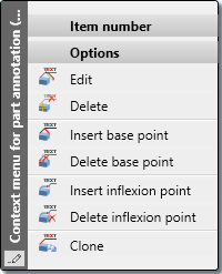
- The Move part annotation function is no longer available. Annotations can now be moved simply by using drag & drop.
- Base points, i.e. additional leader lines, can now also be deleted via the context menu.
- A new feature is the Insert inflexion point function, which allows you to insert inflexion points at the leader lines of an annotation.
- The Delete inflexion point function removes all inflexion points of an annotation.
Views
View marking according to arrow method
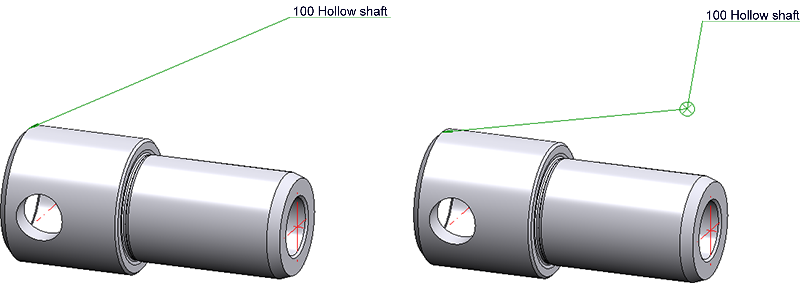
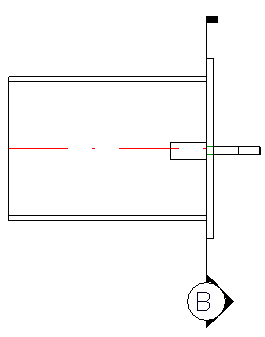
In practice, it is sometimes advantageous to mark views according to the arrow method. This method allows you to represent the viewing direction of a derived view in the original view by the use of a corresponding symbol and a view marking. In mechanical engineering, for example, the viewing direction is marked by an arrow and in civil engineering by a circle with a triangle, with the view marking in the circle.
With the new View marking according to arrow method ![]() function, HiCAD supports this method.
function, HiCAD supports this method.
![]()
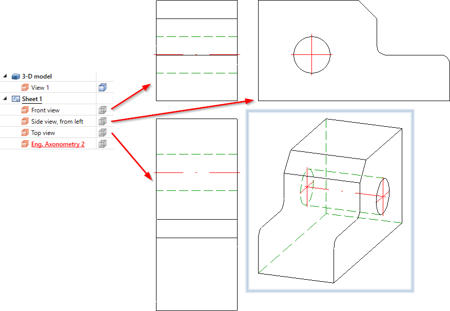
Example:
In the illustration, views of a 3-D model have been generated using the 4 standard views (3-D)  function.
In the following illustration, the front view, the left side view and the top view have been marked according to the arrow method - with the axonometry as the original view.
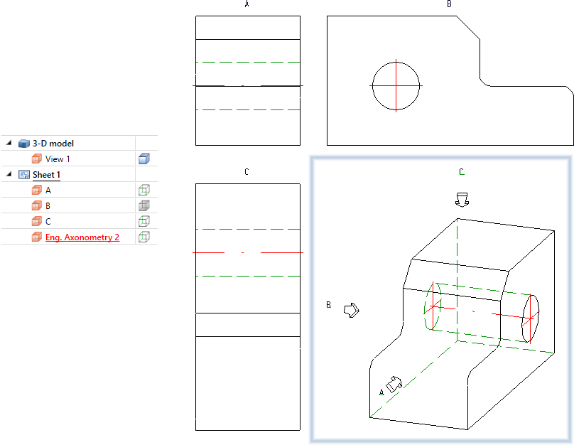
The default settings for view markings can be defined under Drawing > Views > Ident > Arrow method in the Configuration Editor.
View caption
Previously, captions could only be assigned to sectional and detail views. With the new View caption  function, this is now possible for all view types.
The default setting for the position of the caption can be defined under Drawing > Views > Ident in the Configuration Editor.
Sectional and detail views - extended dialogues and options
Based on the new functions View marking according to arrow method and View caption, the dialogues for defining and editing Sectional and Detail views have been revised and extended.
- The identification of the cutting sequence and the annotation of the original view can be configured individually and are visualised directly in the drawing. Annotating can now also be done on one side and with symbols for civil engineering (circle with triangle and rectangle symbol at the end), as well as beside the arrow. In addition, identification can also be done without an arrow.
- The identification of the detail in the original view can be configured individually. As of HiCAD 2022, the Exact detail and Rectangle (filleted) views are also available for outlines of the identification.
- The captions of sectional and detail views an be configured individually.
- The identification of sectional and detail views can be assigned to a specific layer.
- The Detail view Cuboid function also supports identification and annotation of the original view, as well as configurable captions for detail views.
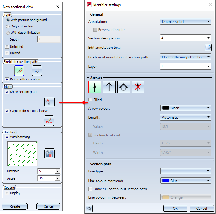
Identification of sectional views
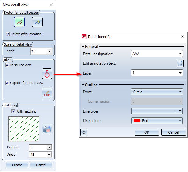
Identification of detail views
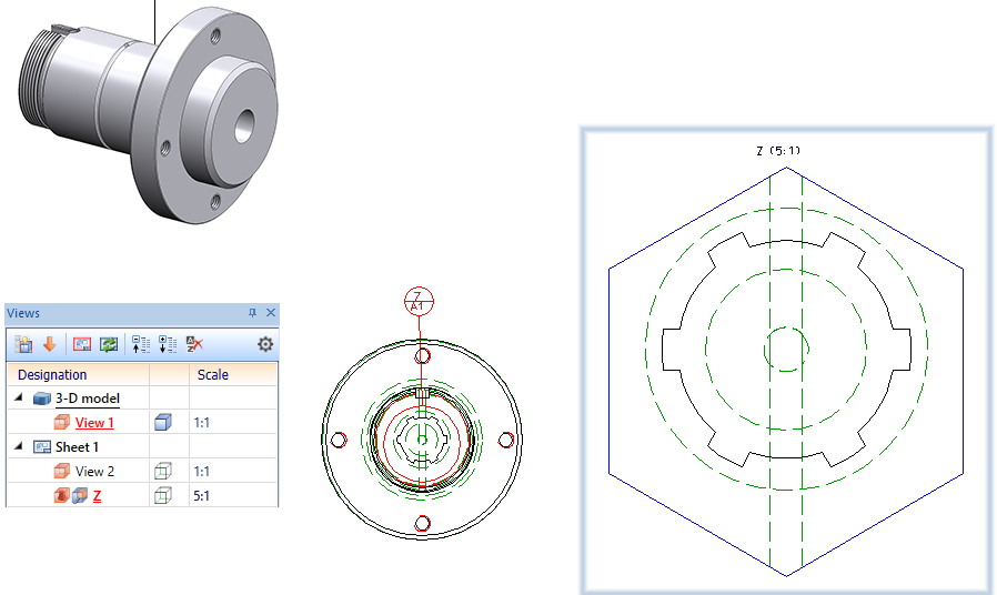
Detail view with exact outline view
The default settings for identification in sectional and detail views can be defined under Drawing > Views > Ident > Sections or Drawing > Views > Ident > Details in the Configuration Editor.
View selection in the ICN
For various view functions, HiCAD requests the selection of a reference view, for example in order to copy data from this view. As an example, this is the case for the functions List from ref. view and Copy shortening. In these cases, the view could previously only be selected in the graphics window and therefore only in the current area. As of HiCAD 2022, the view selection in the ICN is now also possible in such cases.
In this context, the view functions
 Show/unfreeze views, Individual

 Freeze views, Individual
have also been adjusted. The view can now be selected either in the graphics window or in the ICN. The entry of a view number is no longer necessary. Furthermore, the function Select view, via list  has been removed.
Show/Hide elements in view
The dialogue of the Show/Hide elements in view function has changed. The window has been tightened and, instead of checkboxes, the settings can now be selected via different selection boxes.
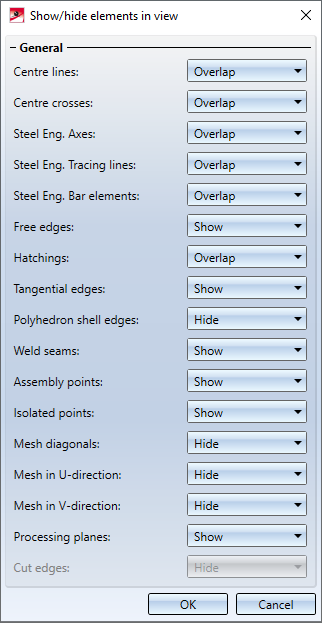
Hiding edges via the limiting angle is no longer available and, as of HiCAD 2022, you use the new Show/Hide edges  function to show/hide any edges of the drawing.
Show/Hide edges
The Show/Hide edges function allows you to show or hide any edges of your drawing in the active view or in all selected views. The settings have an effect on the following representations:
- Glass Model,
- HiddenLine,
- HiddenLine dashed and
- Shaded with Hidden Line.
If the desired edges are to be shown/hidden in multiple views, select the corresponding views in the ICN before calling the function.
After calling the function, the dialogue window Show/Hide edges will be displayed.
Then, select the desired edges in the drawing. Each selected edge will be included in the list in the dialogue window and visualised in colour in the drawing. If an edge that is contained in the list is selected again, it will be removed from the list. In multi-part sheets, when an edge is selected, the congruent edges of the flange and bend zone are also automatically selected.
When clicking on an entry in the list, the corresponding edge in the drawing will be highlighted in colour.
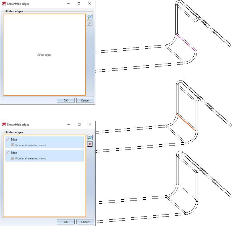
If multiple views were selected when the function was called, it is possible to specify for each edge contained in the list whether the edge is to be hidden only in the active view or in all selected views.
You can hide the edges presented in the list by clicking OK.
When you call the function again, all hidden edges will be listed in the dialogue window. To show the edges again, simply delete the corresponding list entry.
Shaded, without highlighted edges
The new Shaded, without highlighted edges  function provides another representation mode for views. This function shades the parts of the active view and displays all visible edges, with the exception of highlighted edges. Highlighted edges are theoretical edges that occur in places where there is no clear edge due to a rounding.
This display mode can be useful for improving the performance while working on large drawings in the model view.
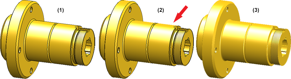
(1) Shaded with edges, (2) Shaded, without highlighted edges, (3) Shaded without edges
You can find these functions
- in the context menu for views,
- in the transparent toolbar and
- under Representation in the View ribbon.
Sectional views with Steel Engineering plates
As of HiCAD 2022, it is also possible to define for Steel Engineering plates whether or not the coating should be marked in the Sectional view, analogously to Sheet Metal parts. The coating is displayed in the form of an offset edge, the so-called coating line. The settings for the representation of the coating line can be found under Drawing > Annotations > Coating line in sectional view in the Configuration Editor.
The representation of the coating line can also be changed subsequently. To do this, right-click on the coating line in the required view and choose the desired function in the Coating symbol context menu.
In addition, if a sectional view is active, the representation of the coating lines can also be changed via the context menu for Steel Engineering. To do this, right-click on the plate in the sectional view and then select the Coating line function under Properties.
Weld seams and weld symbols
- The Insert weld symbol function has been renamed to Free weld seam symbol and provided with a new function icon
 .
. - A new feature is the Annotate weld seam
 function, which you can use to insert weld symbols for existing welds. The function is also available in the context menu for welds.
 - Both the Free weld seam symbol and the Annotate weld seam function are also available under 3-D Dimensioning + Text >Symbols.
Referencing
Path for referenced parts
The Path for referenced parts function in the Drawing > Extras > Temporary settings menu is no longer available. To change the path for referenced parts, open the settings in HiCAD and adjust the folder for the L: identifier under Directories. Then restart HiCAD to make the changed setting effective. The change is specific to the respective workplace and may additionally have to be carried out at all other workplaces.
Internally referenced parts in externally referenced parts
When working with drawings that contain internally referenced parts within externally referenced parts, the behaviour when making changes to internally referenced parts has changed:
-
If the internally referenced part is changed, its identical part is updated and both the identical part and the externally referenced parent part will be identified as a changed part.
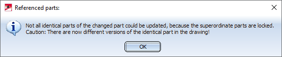
-
The exception to this is if the externally referenced part is locked against processing. In this case, the identical part will not be updated and not be identified as a changed part. In addition, a message will appear, indicating that the part could not be updated and therefore two different versions of the internally referenced part now exist in this drawing:
Miscellaneous
Projection grid
The Projection grid  function in the context menu for processing planes is no longer available.
Purchased and factory standard parts
Previously, it was not possible to incorporate assemblies and parts with subordinate parts from the Purchased/Factory standard parts catalogue. As of HiCAD 2022, this is now supported.
This means that, in addition to assemblies, for example, Sheet Metal parts stored in the Purchased/Factory standard parts catalogue can now be incorporated into the drawing using the Purchased/Factory standard parts  function. However, it should be noted that these Sheet Metal parts are combined into a solid during installation. This means that the installed part will no longer be considered a Sheet Metal part from the HiCAD point of view!
When saving your own factory standard parts to the Purchased/Factory standard parts catalogue, please note the following:
- If you work with your own tables, make sure that these tables are assigned to the Purchased/Factory standard part category. You assign this when creating the table.
- The fitting position must be defined in the parts stored in the catalogue (.KRA files). To do this, you define a Fitting CS. This consists of 3 special points which are automatically assigned the point designations #1 for the origin, #2 for the X-direction and #3 for the Z-direction.
- To save the parts, use the Reference part, Save, Detail drawing
 function.
