Show/Hide Edges
Views > Properties > Show/Hide edges 
This function allows you to show or hide any edges of your drawing in the active view or in all selected views. The settings have an effect on the following representations:
- Glass Model,
- HiddenLine,
- HiddenLine dashed and
- Shaded with Hidden Line.
If the desired edges are to be shown/hidden in several views, select the corresponding views in the ICN before calling the function.
After calling the function, the dialogue window Hide/Show 3-D edges will be displayed.
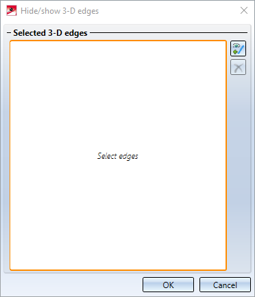
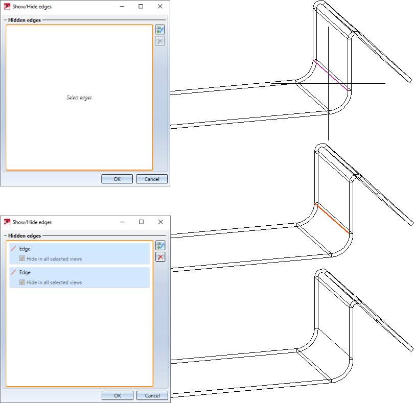
Then, select the desired edges in the drawing. Each selected edge will be included in the list in the dialogue window and visualized in colour in the drawing. If an edge that is contained in the list is selected again, it will be removed from the list. In multi-part sheets, when an edge is selected, the congruent edges of the flange and bend zone are also automatically selected.
When clicking on an entry in the list, the corresponding edge in the drawing will be highlighted in colour.
|
|
Activate edge selection to add more edges |
|
|
Delete the marked list entries, i.e. delete edges from the selection |


If multiple views were selected when the function was called, it is possible to specify for each edge contained in the list whether the edge is to be hidden only in the active view or in all selected views.
You can hide the edges presented in the list by clicking OK.
When you call the function again, all hidden edges will be listed in the dialogue window. To show the edges again, simply delete the corresponding list entry.
![]() Please note:
Please note:
- After changing a part, hidden edges will be displayed again.
- To show/hide special edges, such as centre lines, beam axes in steel engineering, etc., use presets in the Configuration Editor under Drawing > Views > Hiding and overlapping of edges or use the Show/Hide elements
 function.

