New View, Without Link
Views > New > Standard 
You use this function to define a new view without links. In addition, you have the option of defining a list view. A list view is a view in which only certain parts (all parts of a part list) of the drawing are displayed.
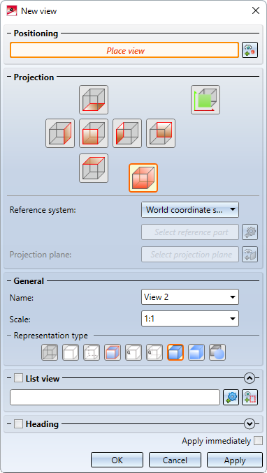
Positioning
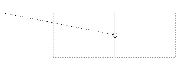
You determine the position of the new view in the drawing under Positioning. For this purpose, a preview of the view frame is displayed, the size of which depends on the selected projection and the parts displayed in the view. In any case, the smallest frame that completely encloses all parts of the view is selected. The view is placed via the focus of the frame. To do this, you can simply place the cursor at the desired point or use the point options of the Autopilot or the Point options menu.
If the placement should be changed, then after clicking on  a kind of rubber band to the last placement point will be displayed.
Projection
In this area of the dialogue window you select the desired projection method. The six standard views
- side view, from left and right
- front and back view
- top and bottom view
as well as the standard axonometry are available for selection.
Standard axonometry and standard views (world coordinate system)
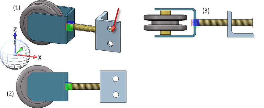
With these projection methods, you can select under Reference system whether the selected projection should be based on the world coordinate system or on the orientation of a particular part. In the latter case, select the desired part.
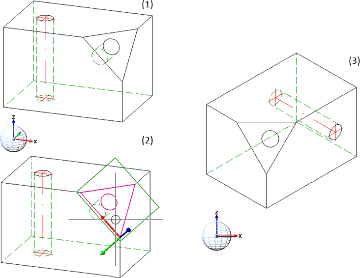
In the following example, the front view of the model (1) has been generated once with the world coordinate system as the reference system (2) and once with the orientation of the threaded rod (3).
Instead of selecting a projection method, you also have the option of selecting a projection plane  . In this case, the new view is rotated so that the selected projection plane is located in the screen plane. After selecting a projection plane, the selection of a reference system will be locked.
The projection plane can be changed before accepting the view by clicking on  .
.
General
Here you select the name of the view, the scale and the display type. HiCAD suggests the name View followed by a consecutive number. You can accept the name or enter a new one.
List view
This function also offers the possibility to create list views. A list view contains only the parts that belong to the active part list. To define a list view, you must first activate the corresponding checkbox.
If a part list is active when the function New view, without link is called, it will be preset. The number of parts belonging to the list is shown in the field below List view.
Above: Original view with 4 parts, below: List view with parts (2) and (4)
If you do not want to use the active part list or if no part list is active, you can select the desired parts in the ICN or in the drawing by clicking on the Select parts  symbol. Please note that a part that has already been selected will be removed from the part list if you select it again.
By clicking on Apply part list of a different view  , you can transfer parts displayed in another view to the part list.
List views are marked with the  symbol in the ICN.
![]() Please note:
Please note:
- In the ICN, all parts hidden in the active view are displayed with reduced colour intensity. The shown parts of a view constitute the part list.
- Standard views become list views if you hide parts in the view in the ICN or use functions of the Show/Hide parts menu.
- You can use the Show/Hide functions of the ICN or the context menu for views to change the list views at any time.
- The behaviour of newly created parts in list views can be changed in the Configuration Editor, under System settings > Visualisation > Views - Include new parts in list views:
- Yes: Newly created parts will be shown in all views.
- No: Newly created parts will be hidden in all list views except for the active view. This is the default setting.
Heading
You can assign a caption to the new view directly when creating it. The entries in the dialogue window correspond to those of the Create/edit/delete view caption(s)  function.
If the Apply immediately checkbox is active, the view is applied directly after placement, i.e. you do not have to click on the Apply button.
If the checkbox is not active, use the OK or Apply button. If you select OK, the view is accepted and the dialogue window will be closed. If you select Apply, the view is accepted but the dialogue window will remain open so that further views can be created. With Cancel you close the dialogue window.
![]() Please note:
Please note:
- To select another projection method, e.g. isometry, first create the view as described above. Then use the Projections function group to select the projection method you want.
- The alignment of views may no longer be standard after interactive positioning. The Rearrange views function enables you to reposition the views subsequently.


Create New View (3-D) • View Functions (3-D) • Views - Basics (3-D)