
The Sketching Tool
The Sketching Tool is a convenient tool for drawing elements of a sketch or a 3D sketch. With this tool you can draw
If a sketch is active, then the Sketching Tool is automatically started when a corresponding drawing function is called.
The Sketching Tool facilitates the construction by the fact that HiCAD - starting from the respective last point of a polyline - automatically displays auxiliary lines along a predefined grid and - depending on the selected mode - shows the corresponding angles, distances or radii at the cursor. On this grid you can
On this grid, for example, you can determine the direction and length of a line with a mouse click by moving the cursor accordingly.
In addition, HCM constraints can be automatically assigned directly while drawing.
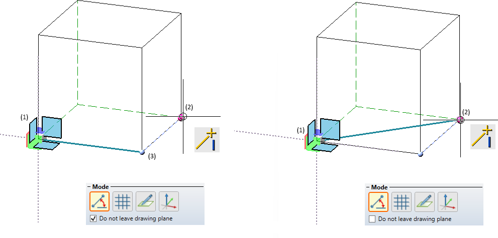
The Sketching Tool essentially behaves in the same way for sketches and 3-D sketches, with one exception: In 3-D sketches, the plane in which drawing takes place can be changed as desired during drawing. This drawing plane is always parallel to the selected plane and runs through the last determined point.
Procedure
- Create or activate sketch
Create - depending on your needs - a new sketch or 3-D sketch. In both cases, you must first select the drawing plane. In the case of a 3-D sketch, the part coordinate system of the sketch is also defined.
or
Activate an existing sketch. - Start Sketching Tool
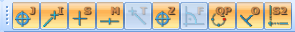
The Sketching Tool is available for all drawing functions whose function symbol has a grid as background:
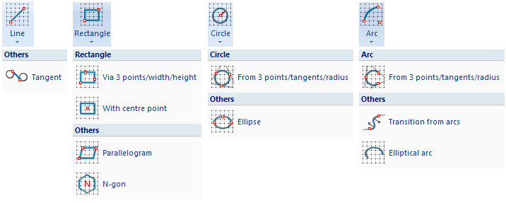
When you call one of these functions, the Sketching Tool is started automatically. The Sketching Tool works similarly for all functions. The following description refers to the sketching of lines. Special features of sketching the different sketching elements are pointed out in the description of the individual functions.
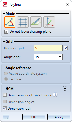
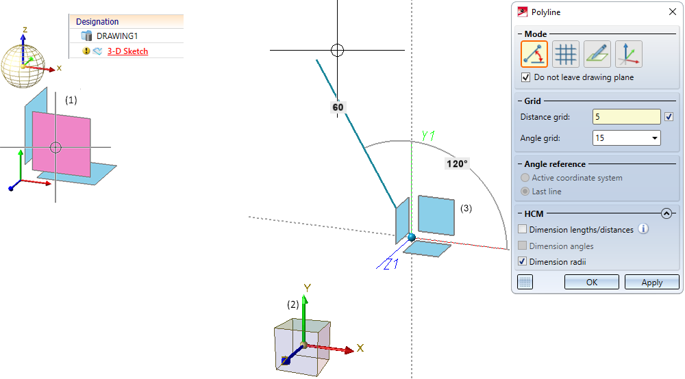
After calling a corresponding drawing function, the Sketching Tool dialogue window is displayed, e.g.:
In the case of sketches, the sketch plane selected when creating the sketch is displayed at the same time, i.e. the plane in which the sketch is drawn.
In the case of 3-D sketches, a plane preview is displayed at the same time in the drawing, which represents the part coordinate system of the 3-D sketch. The current drawing plane when calling the Sketching Tool for 3-D sketches is the XY-plane of this coordinate system. During sketching, the current drawing plane is displayed in a lighter colour.
The X- and Y-axes of the drawing plane are displayed as dashed auxiliary lines, and the point highlighted in blue symbolizes the origin of the sketch's part coordinate system.
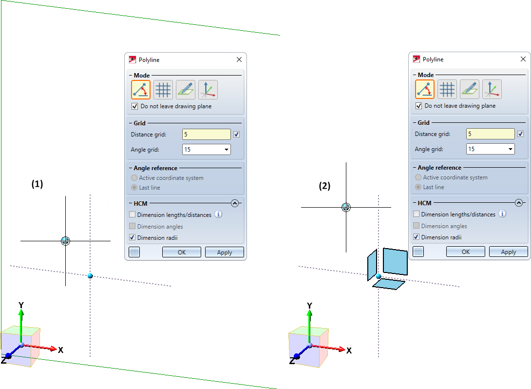
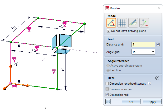
- An example of 3-D sketches:
Suppose you have created a new 3-D sketch and selected the default XY-plane as plane (1). (2) shows the part coordinate system defined by this. If you then call the Line function, the plane preview shown (3) is displayed. After the call, the drawing plane is the XY-plane of the part coordinate system.
- Select start point
The following prompt is displayed in the info bar:
Select start point or plane (MMB = Cancel, RMB = Further options) for 3-D sketches or
Start point (MMB = Cancel, RMB = Further options) for planar sketches.
Now you have the following options:
- Sketch and 3-D sketch
Select the starting point of the polyline. This can be done either by dropping the cursor, by taking over a point found with the autopilot or with another point option. The drawing plane and - in the case of 3-D sketches - the plane preview are automatically moved into this point.
- 3-D Sketch
Change the drawing plane by selecting, in the preview, a plane of the part coordinate system or an existing processing plane in your drawing.
Pressing the middle mouse button (MMB) cancels the sketching tool without generating a polyline.
 If the start point is determined with the point option Online on edge, through point (O) then the relative grid is aligned to the line.
The origin of the part coordinate system is always visualized in the drawing so that you can access it at any time.
- Select following points / context menu
After you have selected the start point of the polyline, proceed likewise to determine the following points. For this purpose, the following prompt is displayed in the info bar:
Select end point or plane (MMB = new polyline, RMB = Further options) for 3-D sketches or
Select end point (MMB = New polyline, RMB = Further options) for planar sketches.
For 3-D sketches you can also change the drawing plane at any time.
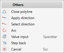
By pressing the middle mouse button you can start a new polyline (in the same sketch). By pressing the right mouse button you can activate a context menu with further options.
|
Functions |
||||||||||||||||||||||||||
|---|---|---|---|---|---|---|---|---|---|---|---|---|---|---|---|---|---|---|---|---|---|---|---|---|---|---|
|
|
This function closes the current polyline, i.e. the last point will be connected to the start point of the polyline by a new line. The sketching tool will remain active afterwards, so that you can directly draw the start point of another polyline. |
|||||||||||||||||||||||||
|
|
With this function the direction of the line shown in the preview is taken over as the direction for the next line to be drawn. |
|||||||||||||||||||||||||
|
|
With this function you can select the direction in which the next line is to be drawn. To do this, specify the direction vector by defining two points, by selecting a straight line or by selecting a surface. If a surface is selected, then the direction is determined by the surface normal. |
|||||||||||||||||||||||||
|
|
With this function arcs can be inserted into the polyline. The start point of the arc is always the last point. You can now draw an arc dynamically with the cursor. The arc radius and the opening angle are displayed at the cursor. First select the radius of the arc. To do this, draw the arc so that the desired radius is displayed and set the cursor down. The direction in which the arc is drawn (tangential or non-tangential) depends on the click position when selecting the function. If you want to use a specific radius, press the space bar or select the Value entry function and enter the arc radius. You determine the arc end point either by setting down the cursor (the opening angle is displayed) or with a point option. If the last determined point is selected again, then the drawing of an arc is started automatically.
|
|||||||||||||||||||||||||
|
|
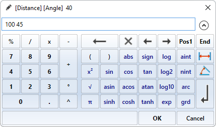
If you want to enter a value, e.g. a length or a radius, explicitly via the keyboard, you can select this function. HiCAD then displays the calculator and you can enter the desired value. Instead of calling the function, you can also simply press the space bar while working in Sketch Technology. In some cases, the distance and angle to the last point or the X and Y distance to the last point can also be entered directly. The two values must be separated by a space.
Which entries are possible depends on the respective function and the mode selected there.
These possibilities do not apply to the start point. |
|||||||||||||||||||||||||
|
|
Step back If you want to jump back one or more input steps to correct the input, select this function (several times, if necessary). Alternatively, you can also use the Undo function during the function dialogue. |
|||||||||||||||||||||||||
|
|
Cancel Cancels the function. |
|||||||||||||||||||||||||


- To complete your polyline, click either OK or Apply in the dialogue. Selecting OK closes the dialogue window. If Apply is selected, the dialogue remains open, allowing you to draw further polylines (of the same sketch)..
|
|
Mode
In this area of the dialogue window you select the sketching mode. During the construction of the polyline you can switch between the different sketching modes as you wish. The following modes are available:
|
|
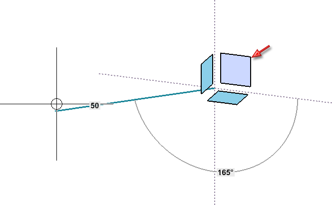
Angle + Distance In this mode (ISD default setting), the angle and the distance to the last point are displayed at the cursor. To determine the following point, place the cursor at the desired position and accept it with the left mouse button. This mode is not available for rectangles, circles, ellipses as well as arcs. |
|
|
XY-grid The X- and Y-distance to the last point are displayed. To determine the following point, place the cursor at the desired position and accept it with the left mouse button. If the Grid checkbox is active at the bottom of the dialogue window, grid points and lines are displayed as construction aids. . This mode is not available for rectangles, circles, ellipses and arcs. |
|
|
Free In this mode you can draw freely, i.e. without a grid. The x and y distance to the last point are displayed at the cursor. To determine the following point, place the cursor at the desired position and accept it with the left mouse button.
Points determined in this mode are always located in the current drawing plane. |
|
|
On axes In this mode you draw on the axes of the current coordinate system. In 3-D sketches, the layer preview is hidden. If the Grid checkbox at the bottom of the dialogue window is active, then grid points are displayed on the axes of the coordinate system as construction aids. |


|
Note:
|
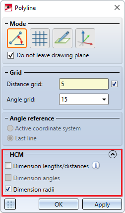
Grid and Angle reference
Under Grid you define the fineness of the distance and angle grid.
Alternatively, the fineness of the grid can also be changed via the keyboard while drawing:
|
Keys |
Effect |
|---|---|
|
+ / - |
Changes the fineness of the distance grid |
|
SHIFT+ /. SHIFT- |
Changes the fineness of the angle grid |
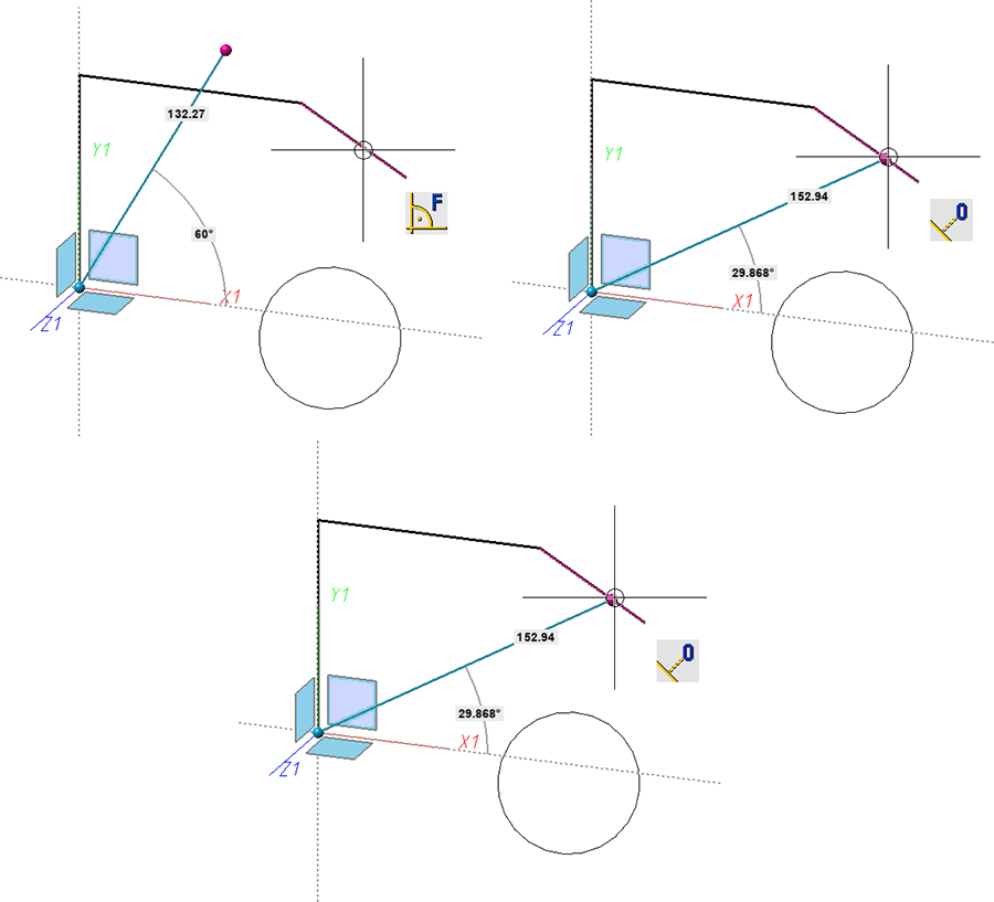
Angle reference determines what the selected angle refers to:
- to the active coordinate system or
- to the last drawn line
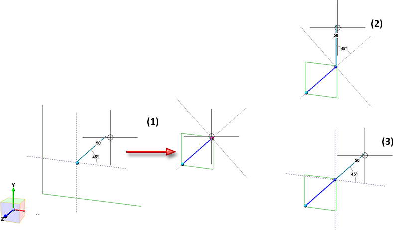
(1) drawing the first line, (2) drawing the following line with reference to the last line, (3) with reference to the active coordinate system
If the checkbox next to the Distance grid field is active, then the value for the distance grid will be automatically adjusted when zooming the drawing. This is the ISD default setting. By deactivating the checkbox, you have the option of specifying individual grid values.
By clicking on the Show grid in graphics area icon at the bottom of the dialogue window - grid points and lines can be displayed as construction aids for determining angles and distances. If the grid is active, the symbol display changes to .
The display of the grid can be changed in the Configuration Editor at System settings > Sketches.
Point options of the Autopilot
When sketching lines, additional options are available for point determination using the Autopilot:
|
|
Displayed when the X-coordinate of the current cursor position is identical to the X-coordinate of another point in the active 3-D sketch. |
|
|
Displayed when the Y-coordinate of the current cursor position is identical to the Y-coordinate of another point in the active 3-D sketch. |
|
|
Displayed when both the X- and Y-coordinates of the current cursor position are identical to the X- or Y-coordinate of another point in the active sketch. For example, you can use this option to select the origin of the part coordinate system as the start point of the polyline. |


Together with the display of the point option, a dashed auxiliary line is also displayed on the point with identical X- or Y-coordinate. All points of the active sketch (start and end points of the lines) as well as the zero point of the sketch are taken into account.
In addition, the point options are displayed on the autopilot - depending on the cursor setting and situation - which are highlighted in colour in the Autopilot Settings toolbar at the bottom of the HiCAD user interface, e.g.:
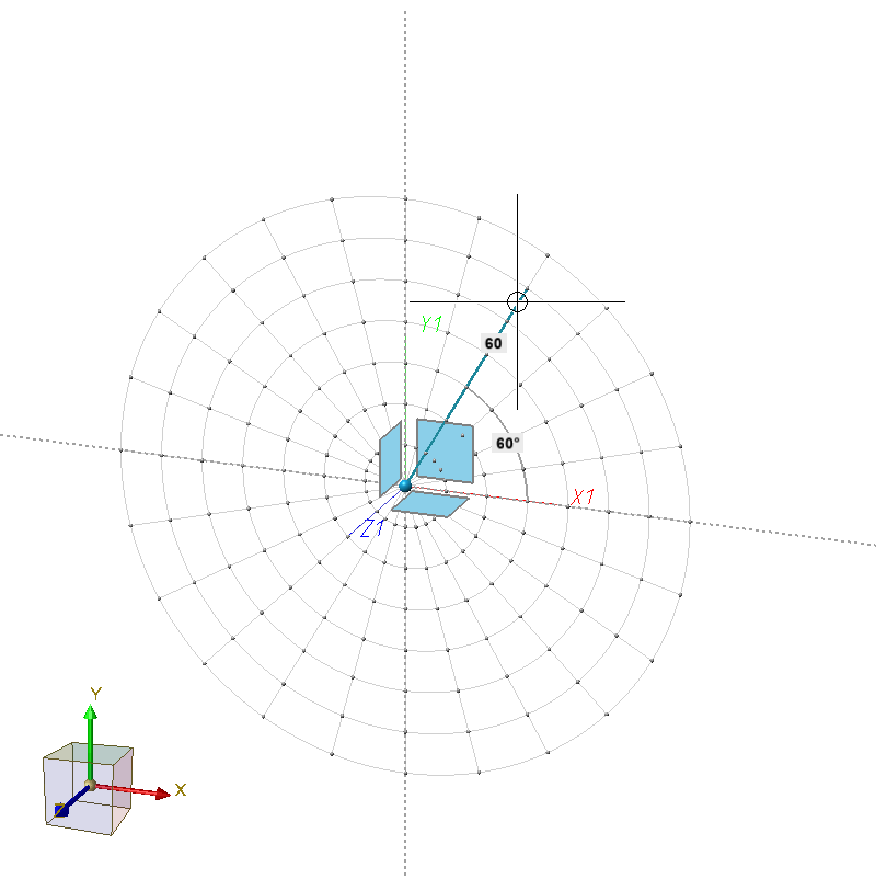
Example of a 3-D sketch using the point option O (Online on line, through point)
In addition to the points in the sketch, the point options X and Y are now also offered for the last point found by the Autopilot (with the exception of the point option O). This does not happen directly when you "run over" a point, but only when you briefly stay on this point with the mouse. This point will then be visualise graphically.
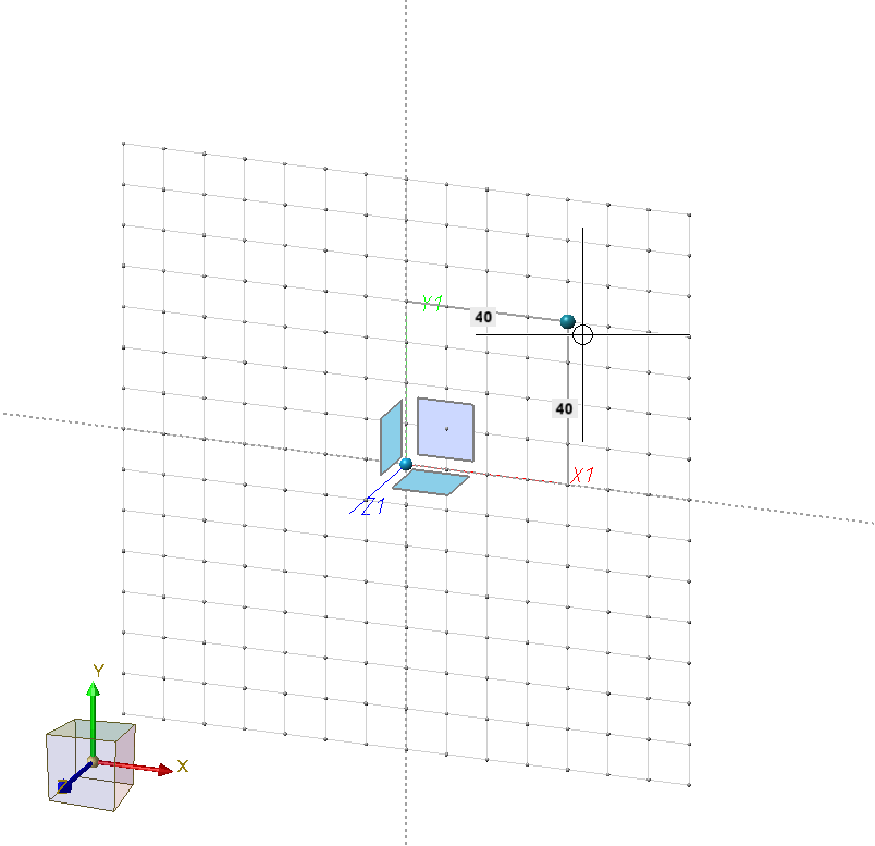
Example:
You move the mouse over the middle of a line. Then the Autopilot will offer the point option Midpoint. However, you do not click but move the mouse further after a short moment. The midpoint will be visualised graphically and from now on the Autopilot will offer the point options X and Y for the coordinates of the midpoint.
![]() Please note:
Please note:
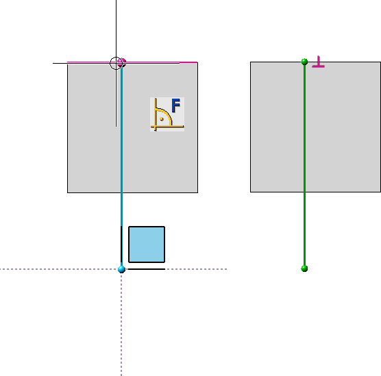
- When determining the start point, the point options T Tangent point and F Perpendicular base point are not available on the Autopilot.
- Note that the X, Y and XY options for 3-D sketches are only available on the Autopilot if the points are in the current drawing plane.
- In contrast to plane sketches, in 3-D sketches the point option T tangent point can be used for circles only if the circle and the last point are in a plane.
HCM constraints
When sketching polylines, circles, arcs and ellipses, the corresponding HCM constraints can also be set automatically. You can activate the automatism directly when drawing the sketch elements, e.g.
The automatic constraints always refer to the part coordinate system.
While drawing sketch elements, this automatism can also be switched off for individual elements by simultaneously holding down the SHIFT key.
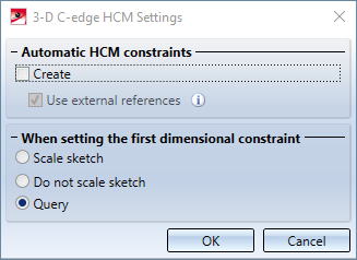
If you want to disable the automatic setting of HCM constraints in general, you have to deactivate the Create checkbox in the HCM settings at Sketch > HCM > Tools
Tip:
For part creation sketches, the best way to draw is to snap or align to the origin. This often already "provides" the constraints to the part coordinate system when drawing. If the Part HCM is used, the part coordinate systems can then be used well, which is a great advantage and in some cases unavoidable.
HCM constraints are preferably set on snapped part geometries, assuming that a sketch is created for the purpose of processing the part. In this case, there is a right angle to the part edge and no parallelism to the Y-axis.
For more information on Sketch HCM, see the Working with Sketches topic and the 3-D Edge Constraint Manager (Sketch HCM) chapter.
Taking into account of Plant Engineering parts
Connecting points of Plant Engineering parts are given special consideration in sketches. If the first point is a connecting point, this point is used to preset a grid direction. This means that the following lines are drawn in this direction.

Working with Sketches (3-D) • Sketch Functions (3-D) • Sketching Tool fpr Planar Sketches (3-D)