Representation Functions
Views > Representation
There are different representation options available for views. They range from the glass model to the hidden line representation, right through to the virtually photo-realistically shaded model. The representation options always refer to the active view, with a few exceptions.
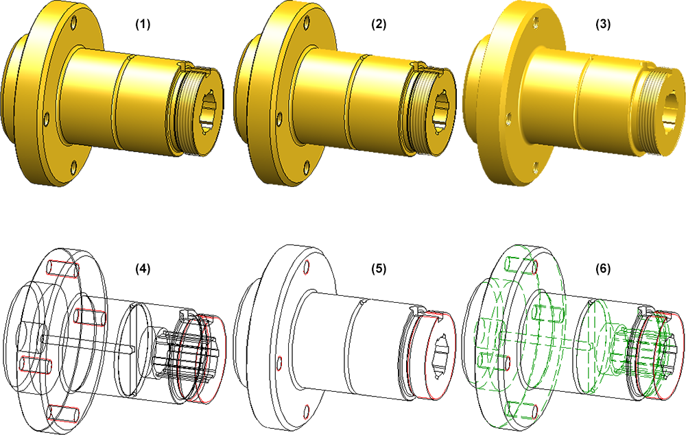
(1) Shaded with edges, (2) Shaded, without highlighted edges, (3) Shaded without edges, (4) Glass model, (5) Hidden Line, (6) Hidden Line dashed
|
|
Shaded with edges Shades the parts of the active view. The visible edges are displayed. If there is no setting of the shading parameters, material file M_HiCAD and Parallel lighting from the front is assumed. The edges are displayed according to the currently set edge model parameters. Clicking
|
||||||||||||||||||
|
|
Shaded, without highlighted edges Shades the parts of the active view. The visible edges, with the exception of highlighted edges, are displayed. Highlighted edges are theoretical edges that occur in places where there is no clear edge due to a rounding. This display mode can be useful for improving the performance while working on large drawings in the model view. |
||||||||||||||||||
|
|
Shaded without edges Displays all parts of the active view as shaded. The part edges are hidden. |
||||||||||||||||||
|
|
Sets all edges, also the hidden ones, to visible. It is called "glass model", because the setting is only realistic for transparent material. The image build-up speed is one advantage of this representation, as no visualisation calculations need to be performed. |
||||||||||||||||||
|
|
Hides hidden edges. |
||||||||||||||||||
|
|
Hidden Line dashed Displays hidden edges as dashed. The hidden edges of a body lying on level 40 (glass) are not considered here. |
||||||||||||||||||
|
|
Quick Hidden Line Displays edges in the surface colour and hides hidden edges. |
||||||||||||||||||
|
|
Quick Hidden Grey Displays edges in the surface colour and hidden edges in grey. |
||||||||||||||||||
|
|
Show only active view Hides all views except the active one. |
||||||||||||||||||
|
|
Show all views Redisplays all hidden views. |
||||||||||||||||||

 opens a menu with further representation functions:


Change representation in multiple views
If several views are selected in the ICN, the display of all selected views can be changed in one step.
Note the following:
- The progress bar is view-comprehensive. This also applies to aborting hidden line calculations with the ESC key. Views that have not yet been calculated are then displayed in QuickView.
- If the display function is called with the CTRL key pressed, the views are always switched to exact representation. This also applies when the automatic QuickView is active.
- If several views are selected, all of which already have the desired display, but are in QuickView, HiCAD asks whether the views should be switched to exact representation.

Please also read the information given in the QuickView vs. Exact Representation topic.
 Please note:
- The options Glass Model, Quick Hidden Line, Shaded with edges, Shaded without edges and Shaded, without highlighted edges can also be called via the transparent toolbar.
- The functions can also be called via the context menu for views.
- Hatchings and edge colours of 3-D parts are taken into account in visualisation and shading functions, as follows:
- Hatchings: always
- Edge colours: for the Glass Model, Hidden Line, Hidden Line Dashed and Shaded + Hidden Line functions.
- You can assign 3-D parts a special setting for individual views. To do so, select 3-D Standard > Properties > Others > Properties in view.
- Further shading function can be accessed via Drawing > Others > Extras > Tools.
- Please also read the information on the Hidden Line collision check.
- Colour, line type and layer of hidden edges can be preset in the Configuration Editor at Drawing > Views. If you choose Layer -1 (Default), the layer will be automatically determined by HiCAD. This depends on the question to which part the corresponding edge belongs.
- Centre lines, cross-hairs and Steel Engineering axes are always displayed as red dashed lines in Hidden Line dashed representation. The overlap settings defined via Views > Properties > Show/hide elements will be ignored, as well as the corresponding pre-settings in the system file ansgen.dat. In contrast to this, the Hidden Line representation respects the overlap settings for centre lines, cross-hairs and Steel Engineering axes defined via Views > Properties > Show/hide elements.


Views (3-D) • Show/Hide Parts (3-D) • Colour and Lightning (3-D) • Shading Functions (3-D)