Divide Surface

With this function you divide surfaces of the active part. For example, the side of a sheet can be divided into two surfaces that can be addressed separately and thus can also be coated, coloured or hatched differently. The division of the surface can be done on the basis of a planar sketch or by determining a polyline.
After calling the function, the dialogue window shown will be displayed.
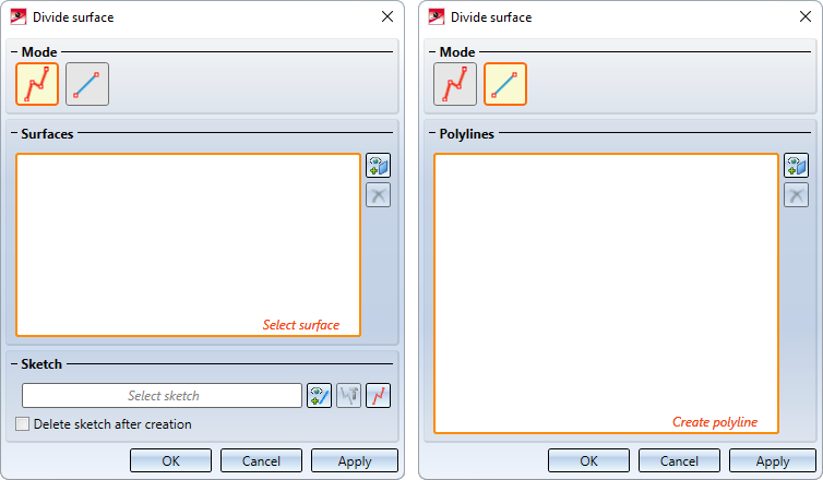
Two modes are available for dividing surfaces.

Use sketch for dividing 
In this mode a sketch is used for dividing. The lines are drawn out internally in the Z-direction of the sketch to form surfaces and are intersected with the surfaces to be divided. Each intersection curve that is closed or goes from edge to edge splits the surface into two pieces. Lines ending in a surface are extended there to enable dividing.
If this mode is active, HiCAD prompts you to select the surfaces to be divided. This can be done by simply clicking on the surface or by selecting two lines belonging to the surface. The two lines must form a surface boundary cycle.
In addition, you can use the right mouse button to activate a context menu with further selection functions.
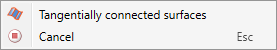
| Tangentially connected surfaces |
Activate this function if all tangentially connected surfaces should be taken over for the next selected surface.
|
All selected surfaces will be marked in colour and for each surface the entry Surface will be added to the list in the dialogue window. If an already selected surface is selected again, the surface will be removed from the list. To remove entries from the list, select the entries and then click on Remove selected surface  . Alternatively, you can right-click on a list entry and then select Remove element(s) from list in the context menu.
The area selection can also be expanded or reduced by clicking on the  symbol.
Once you have selected all the areas to be divided, you must determine the division sketch. The following options are available for this:
|
|
Select sketch Click on the icon to select an existing sketch. |
|
|
Process sketch With this function, a previously selected sketch can be edited. The Process sketch dialogue window will be displayed for this purpose. Change the sketch as desired and click on Apply sketch in the dialogue window. The dialogue will continue with the changed sketch. |
|
|
New sketch in plane With this function you can create a new 3-D sketch that will then be used for dividing. Create the desired sketch and click on Apply sketch. The dialogue will continue with the new sketch. |


If the initial sketch should be removed from the drawing after the creation of the part, activate the checkbox Delete sketch after creation.
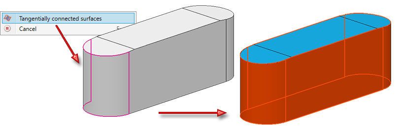
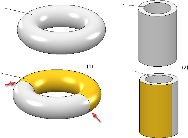
In the following example, the part (1) was divided via the sketch. After calling the function, the option Tangentially connected surfaces was selected, then the surface (2) and the sketch (3) were selected. (4) shows the result.
|
|
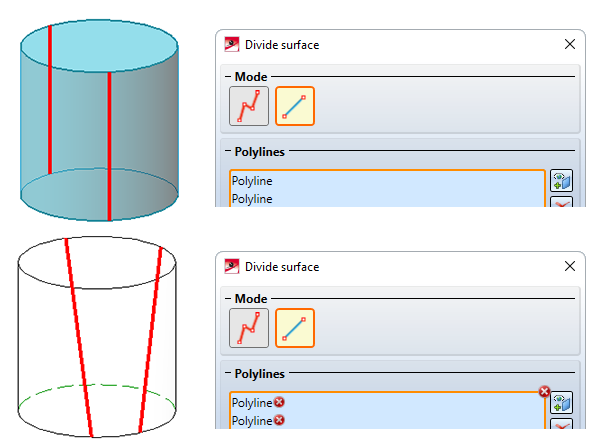
Use polyline for dividing 
In this mode, instead of a sketch, polylines consisting of straight lines one at a time are used for dividing. These lines must lie exactly on the surface that is to be divided. As a result the surface will automatically be specified and does not have to be explicitly selected. Surfaces as well as cylindrical and conical surfaces can be divided.
The polylines are precisely defined by their corner points and thus by point options. Determine the points of the polyline and apply the polyline with the middle mouse button. For each applied polyline, the entry Polyline will be added to the list in the dialogue window.
Please note the following:
- If there are multiple polylines located in one plane, each polyline must be taken over with the middle mouse button. A list entry is created for each polyline.
- If the lines of the polyline are located in different planes, the polyline can be taken over as a whole with the middle mouse button. For example, polylines can also be drawn "around the corner".
- The lines must not intersect.
- Freeform curves are also permitted.
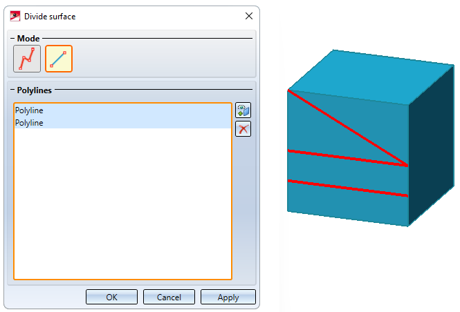
Example 1:
Here, two polylines are located in one plane. Each of these polylines must be taken over with the middle mouse button.
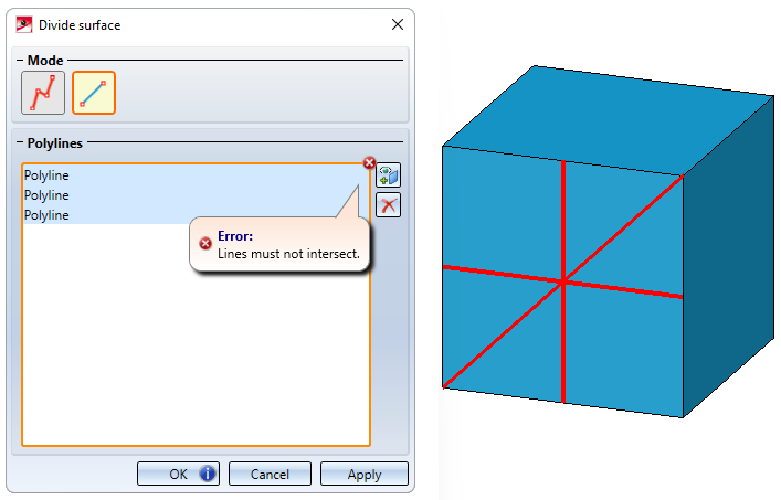
Example 2:
In this example, there are three lines located in one plane. The division will not be carried out because the lines intersect.
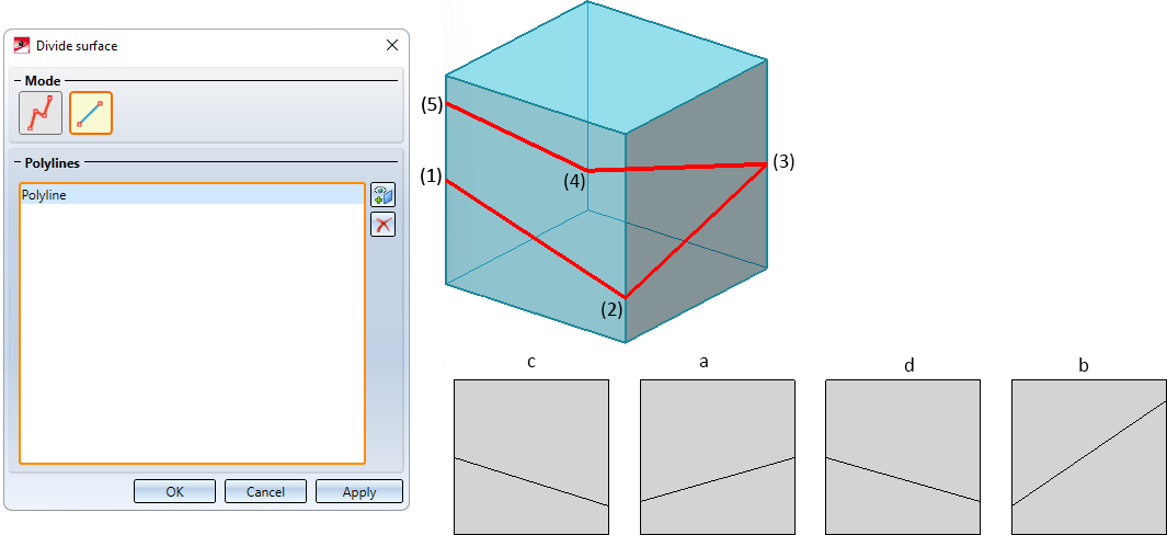
Example 3:
Here a polyline is drawn "around the corner". The start point of a line is the end point of the previous line, each of the four lines is located in a different plane. The division is carried out. Here the polyline divides the front (a) and back (b) as well as the right (c) and left side (d) of the cuboid in one step.
By right-clicking on a list entry and then selecting the Remove element(s) from list function, entries can be deleted.
The polyline selection can also be expanded or reduced by clicking on the  symbol.
|
|
Perform division
If the division cannot be carried out, for example because the selected polyline is not suitable, the  symbol will be displayed on the OK button. If the selected polyline does not meet the requirements, the
  symbol will appear next to the polyline in the list. If you point to one of the symbols with your cursor, you will receive further information. The corresponding lines and surfaces will be visualised in the drawing and highlighted in red. You can then cancel the entries or the function.
When clicking on Apply, the dialogue window will remain open after dividing so that you can divide further areas without having to call the function again. The dialogue window is closed with OK .
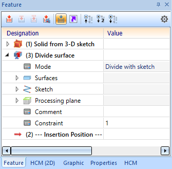
A feature with the name Divide surface is created for each division. Double-click on the entry in the feature log to start the Divide surface function dialogue, for example to process the sketch on which the division is based, to change the surface selection or to select a different polyline.

Further Surface Functions (3-D) • Surface Functions (3-D) • Model and Process Parts (3-D)