3-D Standard > Process > Trim  > Divide along direction
Steel Engineering > Lengthen > Divide > Divide along direction 
This function allows you to divide parts of the type Solid into several sections along one direction. Different division options are available, for example, the individual parts can have different lengths. In addition, a corresponding feature is created with this function so that the division can also be edited later.
|
Before using either function, please note the following: The two functions essentially work in the same way except for the following differences:
|
Topics:

The dialogue window
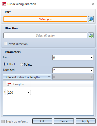
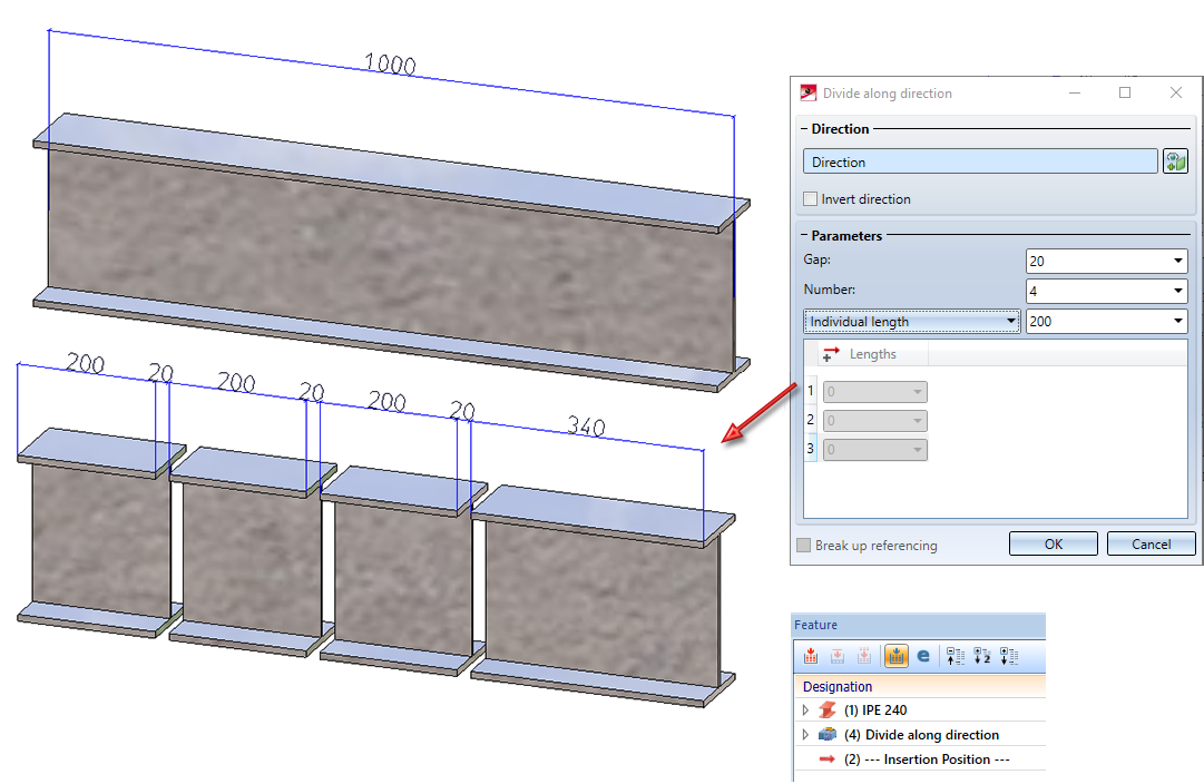
For defining the subdivisions the following dialogue window will be displayed:
Part
The system will always choose the active part for processing, with the name being displayed under Part. If the function is called while an invalid part is active (e.g. a dummy part), the text Select part will be displayed instead of the part name. In this case, you can select the part to be processed directly in the ICN or in the drawing. If you want to process a part other than the one displayed, click on the  symbol and select the desired part in the ICN or in the drawing.
Direction
If a part is selected, the Select direction field will be activated automatically (highlighted in colour). Then determine the direction in which the division is to be made. This can be done by selecting two points, an edge or a surface. If a surface is selected, then the surface normal is used as direction. The selected direction is visualised by a coloured arrow in the drawing.
With Steel Engineering beams, the beam axis is automatically suggested as the division axis. For the 3-D function, the direction runs from the start point to the end point of the beam axis. For the steel engineering function, the direction is determined by the current cursor position when the function is called.
To change the direction, click on the Select direction  symbol.
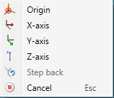
While selecting the direction, you can right-click to activate a context menu with additional functions.
If the displayed direction shall be reversed, activate the Invert direction checkbox.
Parameters
|
Global parameters |
|
|
Gap |
Distance between two segments |
|
Break up referencing |
If the original part is referenced, the referencing can be broken up by deactivating the checkbox. When breaking up the referencing, a HELiOS document and article master existing at the original part is also deleted. If the checkbox is active, the referencing is assigned to the first part in the direction of the division. This also applies to a HELiOS document/article master existing at the original part. The other parts are not referenced. |
|
Division via distance specification |
|
|
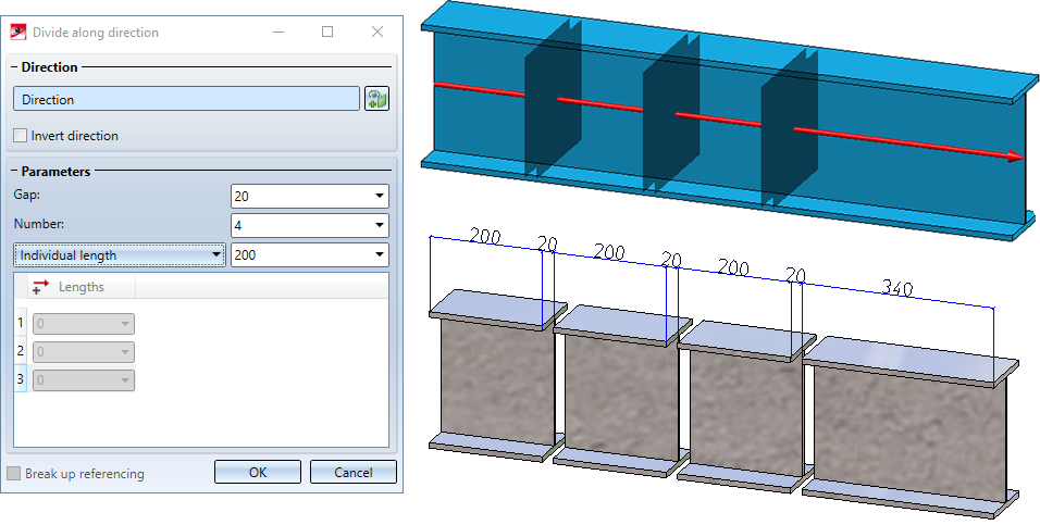
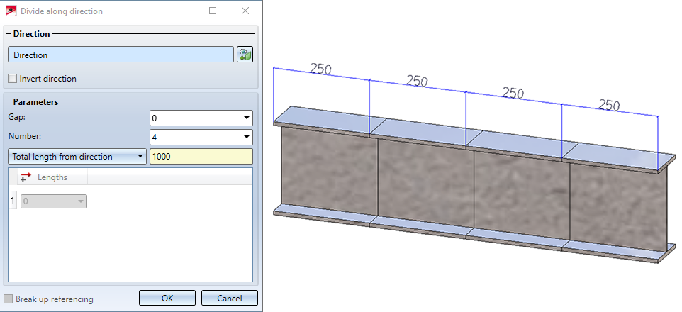
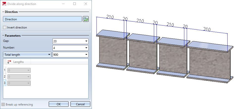
Number |
Number of segments |
|
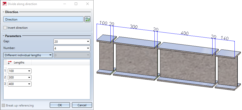
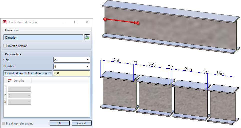
Length of segments |
To determine the length of the segments, the selection box offers various possibilities. Please note that the total length of the resulting segments + gap always corresponds to the total length of the original part. This means that the length of the last segment is calculated automatically and may differ from the individual length specified.
|
|
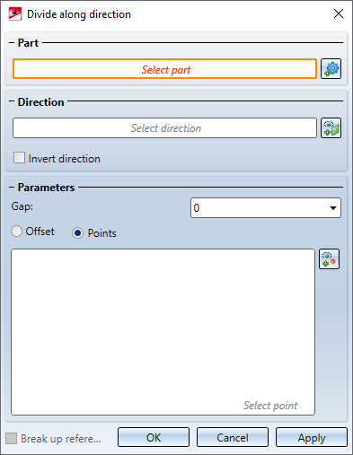
Division via point specification |
|
|
|
Here you can select the division points specifically by clicking on the symbol. For this you can use both the point options of the Autopilot and those of the Point options menu. For each selected point, a line of points is entered in the list of the dialogue window.
The division points do not have to be on the part, e.g.
To remove a point from the list, right-click on the corresponding entry and select the Remove element(s) from list function. |

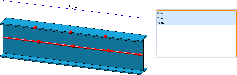
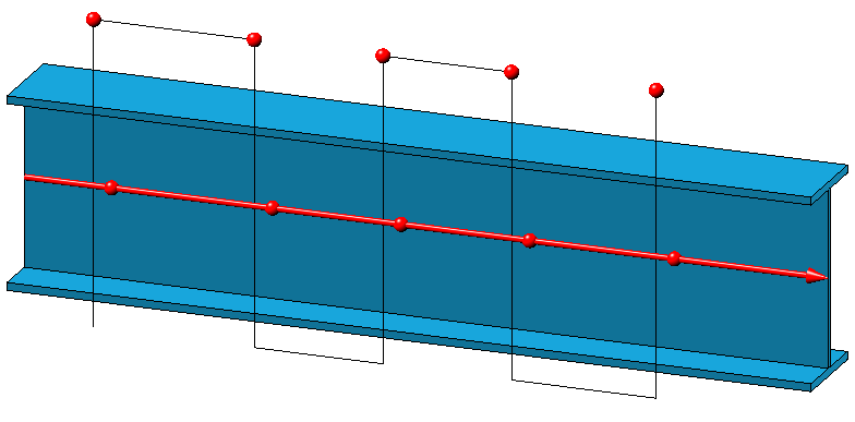
The direction, each division point, each gap and the parts created by the division are immediately visualised in the drawing.
Incorrect or missing entries are marked with the  symbol. If you move the cursor over the symbol, a corresponding message is displayed. If the function cannot be executed with the entered data, this is indicated by the
  symbol on the OK button at the bottom of the dialogue.
Execute the division with a click on the OK button. You can also press the middle mouse button. The dialogue window will close after dividing.
It is also possible to execute the division by clicking Apply. However, the dialogue window remains open in this case. You are then able to edit further parts. Press the middle mouse button to terminate the function.
The Divide feature
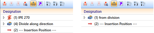
Each resulting part is a separate part in the part structure - on the same hierarchical level as the original part and with the same name. The (processed) original part receives a feature with the name Divide along direction. This is the main feature. All other parts receive a feature with the name from division. These are the dependent features.
If the main feature is selected in the ICN, in addition to the original part, all associated segments in the drawing are also highlighted in colour. This also applies vice versa.
By double-clicking on one of the features, the division can be edited subsequently. All parts are adjusted accordingly.
Please note the following:
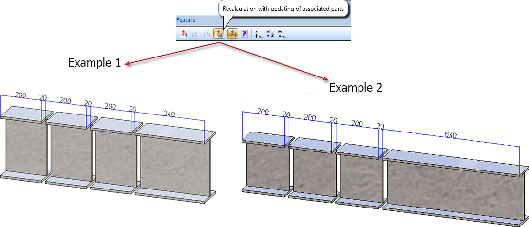
If you change changes, for example the number of divisions, directly in the feature log, then the calculation and update of the division is carried out directly. If variables are used instead and these are changed, then the recalculation with updating of the division must be triggered manually. To do this, use the Recalculation with updating of associated parts  function in the toolbar of the feature window in the ICN.

If the main feature Divide along direction is activated / deactivated, the associated features from division are also automatically activated / deactivated. At the same time the dependent parts will be recalculated accordingly, i.e.:
- If the main feature is deactivated, the original part will be restored and the segments will become dummy parts.
- If the main feature is activated, all segments will be restored.
![]() Please note:
Please note:
- The functions are also available in the context menu for 3-D parts and Steel Engineering beams and profiles.
- The total length of the resulting parts (+ gap) always corresponds to the total length of the original part.
- If the original part (not referenced) has a HELiOS document and article master, then this master is also assigned to the parts.
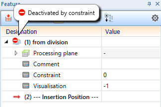
- If a feature is deactivated by setting the constraint to 0, this will be indicated by a corresponding symbol on the feature.
Please also read the notes in the Update division feature paragraph further down.
Examples
Example 1: Divided beam
Example 2: Divided beam - Direction through 2 points
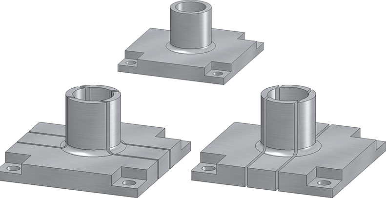
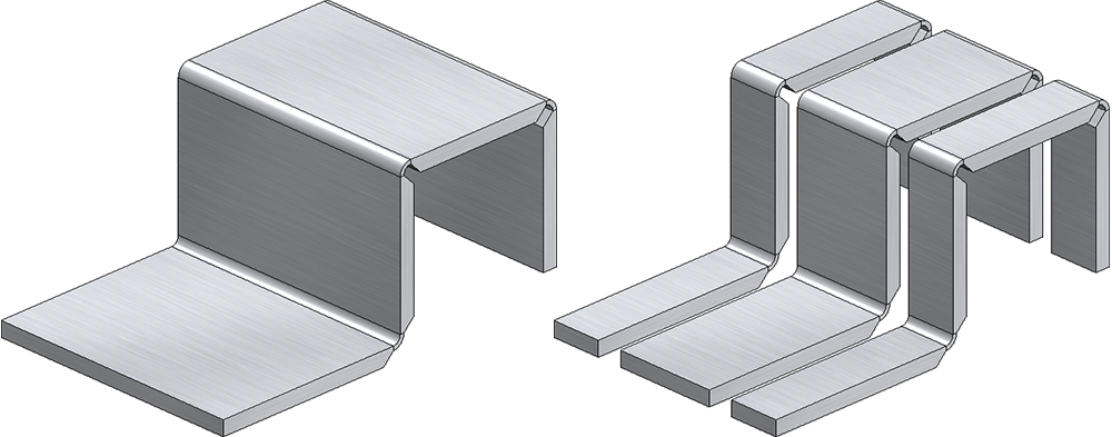
Example 3: Divided 3-D part
Example 4: Divided Sheet Metal part
Changes to the original part
If you make changes to features on the original part that were created before the Divide along direction feature, then only the original part is recalculated. The division is carried out at the same point in relation to the part coordinate system. This means that neither the division points nor the segments are automatically recalculated.
To update the other segments as well, use the Recalculation with updating of associated parts function in the toolbar of the feature window in the ICN.
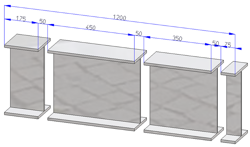
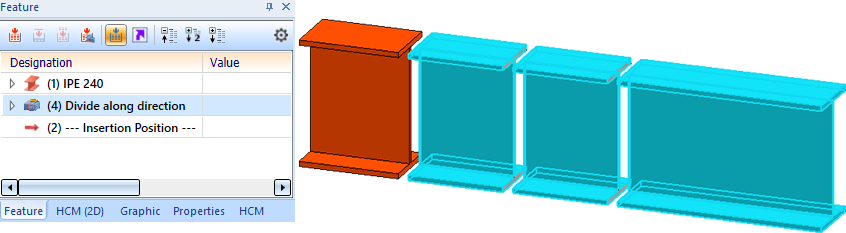
Example 1:
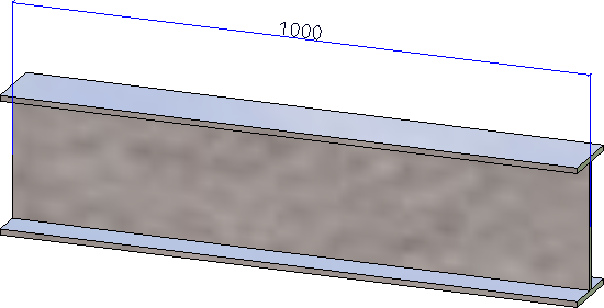
The following figure shows a divided IPE 240 beam.
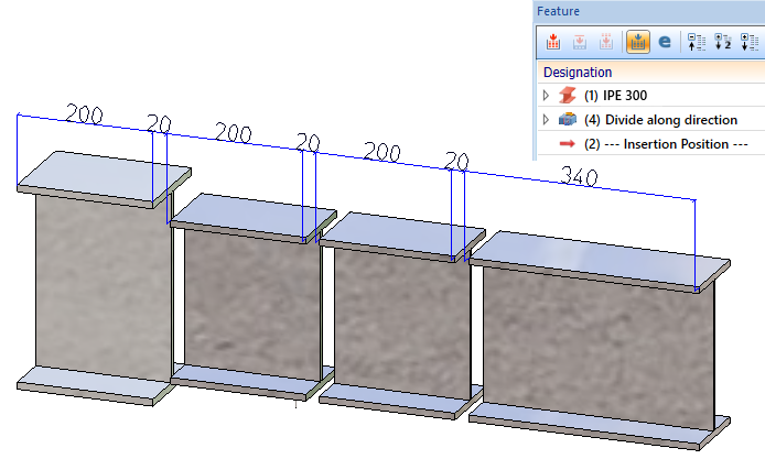
If you exchange the beam, e.g. with an IPE 300 beam, you get the following result:
To update the other segments as well, use the Recalculation with updating of associated parts function in the toolbar of the feature window in the ICN.
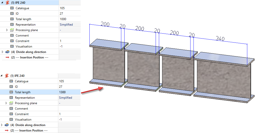
Example 2:
Again we take a look at the image from Example 1. If the total length of the beam is changed by the feature, no geometric change is visible.
To update the other segments as well, use the Recalculation with updating of associated parts function in the toolbar of the feature window in the ICN.
A recalculation of all parts takes place automatically when you change the part feature.
