Dialogue Window for Sectional Views
Views> New >
Sectional view 
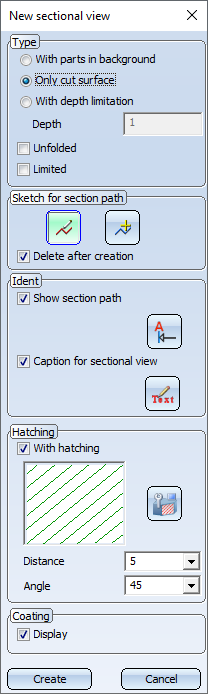
You make the settings for sectional views in the New sectional view dialogue window, which is displayed automatically when you call the Sectional view function.
Topics:

Type of the sectional view
![]() With parts in background
With parts in background
The view is displayed as a solid.
![]() Only
cut surface
Only
cut surface
A sectional view is created in which only the cut surface is displayed.
![]() With depth limitation
With depth limitation
If this option is active, the depth of the section does not extend over the entire drawing, but the cutting depth is explicitly determined by the specified value. The value for the depth determines the distance from the cut surface up to which parts are to be represented.
If the ![]() Unfolded checkbox is additionally active, all cut surfaces are unfolded into a common plane. This is useful, for example, if you want to display the inner sides of revolved parts, pipes, etc. In addition, non-unfolded views can be limited laterally, so that the section object does not penetrate the drawing entirely.
Unfolded checkbox is additionally active, all cut surfaces are unfolded into a common plane. This is useful, for example, if you want to display the inner sides of revolved parts, pipes, etc. In addition, non-unfolded views can be limited laterally, so that the section object does not penetrate the drawing entirely.
You can limit non-unfolded sectional views laterally by activating the ![]() Limited checkbox. In this case the view would be a combination of a sectional and a detail view. After closing the dialogue window for sectional views the dialogue window for detail views is displayed automatically. Here you can specify the scale and the hatching parameters.
Limited checkbox. In this case the view would be a combination of a sectional and a detail view. After closing the dialogue window for sectional views the dialogue window for detail views is displayed automatically. Here you can specify the scale and the hatching parameters.
 If you want to change the lateral limitation of a sectional view subsequently, use the Change detail view function. This function displays the automatically created limiting frame as a sketch. You can change this sketch subsequently, i.e. move or rotate it.
 If a sketch that has been parameterised with HCM constraints contains variables, these will automatically be defined as variables of the view. When using the sketch in a detail view, a sectional view or a cut-out. If you then change the value of the view variables, all views of the current drawing will be updated and the corresponding detail views, sectional views and cuts-outs will be adjusted accordingly. The original sketch, however, remains unchanged. This means that you can adjust view fast and easily without having to change the corresponding sketch.
Sketch for the section path
The path of sectional views is based on a 3-D sketch. This may be available in the drawing or be newly created when defining the view.
|
|
New sketch |
Activate this icon to create a new sketch. |
|
|
Select sketch |
Activate this icon if you want to use a sketch that is available in the drawing. Then identify the relevant sketch. |
|
|
Delete after creation |
The sketch used is preserved even after the sectional view has been created. |
|
|
The sketch used is deleted after the sectional view has been created. |


Please also read the notes on the purposes and representation of sketches. Sketches with the purpose Part will be cut in sectional views, sketches with the purpose Create/Edit will not be cut.
Identification of sectional views
In this area you determine whether the section path is to be represented and if the sectional view is to be provided with a caption. Activate or deactivate the corresponding checkbox.
|
|
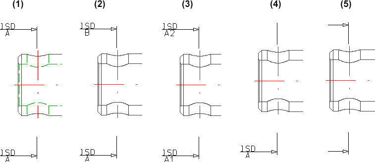
The section path is identified. The ISD default settings are:
|
|
|
Use the Change text and line parameters button to define the identification of the section in the original and in the active view. These parameters are, among others, the symbolic representation of the viewing direction, content and position of the annotation as well as the representation of the section path. |
|
|
If this checkbox is active, a caption will be generated for the sectional view. The ISD default setting is the section designation, which is also used as view name of the sectional view. |
|
|
If you want to define an individual view caption, click on the Edit view caption button. |
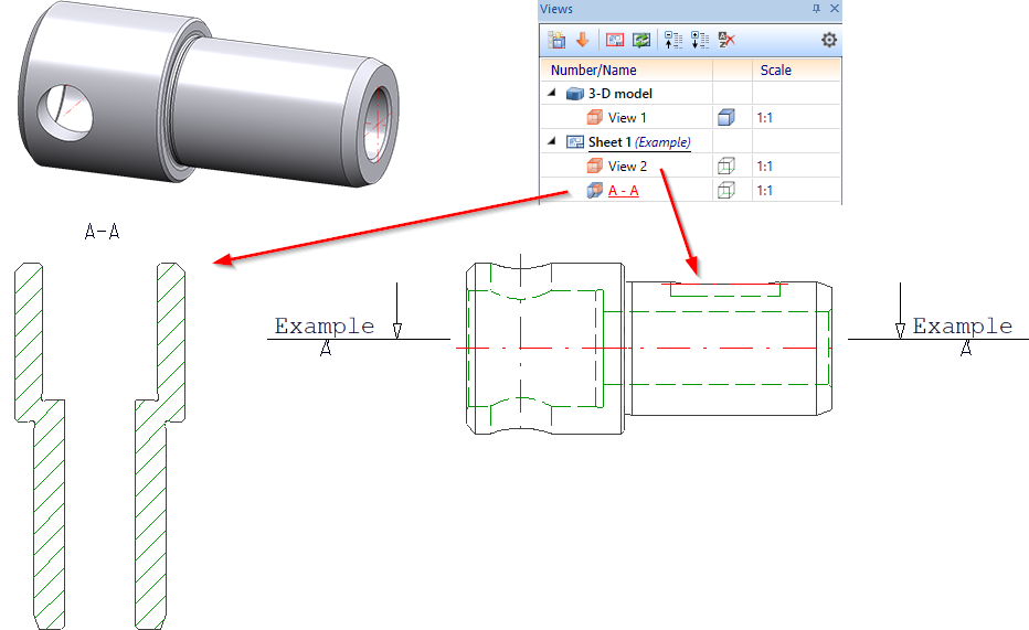
Example - Default settings
Section path - Change text and line parameters

In the Identifier settings dialogue window, you can set the parameters for the annotation and representation of the section path in the original view.
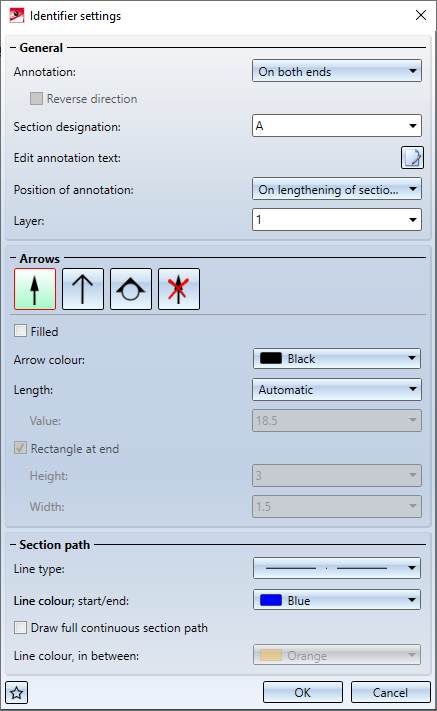
The identifier settings are displayed as a preview in the drawing - provided that the sketch has been selected beforehand.
The current settings of the dialogue window can also be saved as favourites for later reuse. To do this, click on the  symbol at the bottom of the dialogue. You can find out more about managing favourites under Favourites in the HiCAD Basics Help.
|
General |
|
|---|---|
|
Annotation |
This setting determines how the annotation should be done. The following settings are possible:
For Consecutive letters and Consecutive numbers, the direction can be reversed by activating the corresponding checkbox. For One-sided annotation, you can change the side. If Circle with triangle is selected as the symbol, only one-sided or double-sided annotation is possible. |
| Section designation |
You determine the section designation via direct input or selection in the listbox. If you have used capital letters or numbers in view markings in the sectional views of the drawing, HiCAD will automatically suggest the smallest capital letter or the smallest number not yet used for the section designation. Views that only have a caption (without a designation in an original view) are also taken into account. Whether a letter or a number is suggested depends on the last designation used. For example, after a sectional view with the designation A, a letter will be used again for the next sectional view, and after a sectional view with the designation 1, a number will be suggested again. |
| Edit annotation text |
The ISD default setting for the annotation text is stored in the ViewOriginLabel_Section.ftd file in the HiCAD SYS directory.
If you want to change the default annotation text, click on |
| Position of annotation |
This setting determines the position of the annotation in relation to the section path. The following options are possible:
Left: position of the annotation in extension of arrow, Middle: on lengthening of section path, Right: beside arrow |
| Layer |
Here, you define on which layer the annotation should be stored. |
|
|
|
|
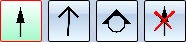
Arrows |
|
|
Here you determine which symbol is used for identification:
It is also possible to fill the closed arrow as well as the triangle. If you have selected the one-sided annotation, the Rectangle at end checkbox will be available for the Circle with triangle symbol. If the checkbox is active, a rectangle of the specified size will be drawn at the end point of the section path.
If the original view is a 3-D view, e.g. an axonometry, the selection of symbols will have no effect. In this case. a 3-D arrow will always be used. |
|
Arrow colour Length |
Here you select the colour and length of the arrows / symbols. The length can be determined automatically by HiCAD or explicitly by entering a value. |
|
Section path |
|
|
|
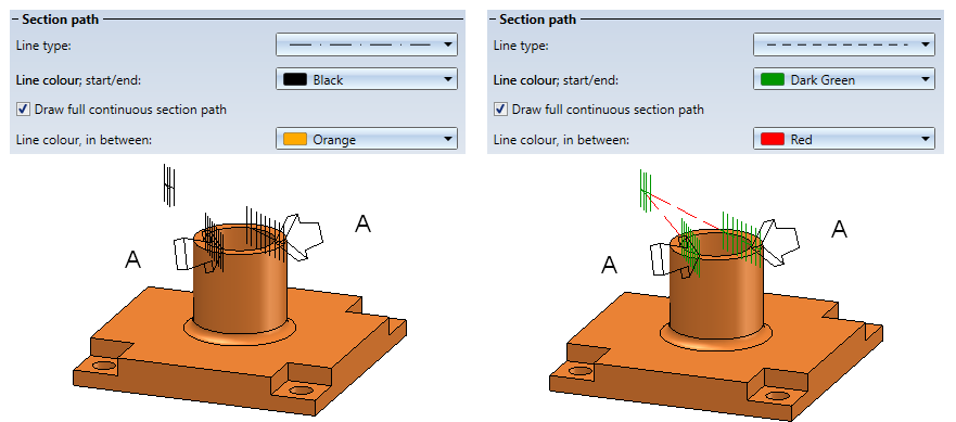
In this area of the dialogue window you determine the representation of the section path.
Different representations of the section path - here on a 3-D view
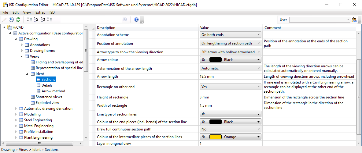
When calling this function for the first time within the current drawing, the settings from the Configuration Editor are used as default settings in the dialogue window (Drawing > Views > Ident > Sections). For further calls of the function, the last used text and line parameters are used as default. |
 . You can then define and format the text as in the
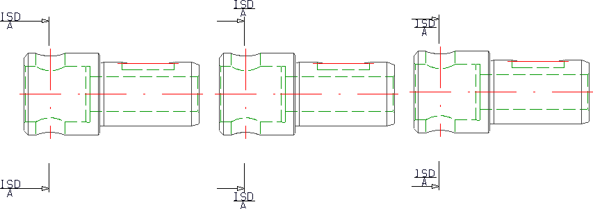
The representation of the section path and the identification of the section in the original view also depend on the settings under Drawing > Views > Ident > Sections in the Configuration Editor.
Edit view caption

If you do not want to use the ISD default settings for the caption of a sectional view, you can define individual captions by clicking on .
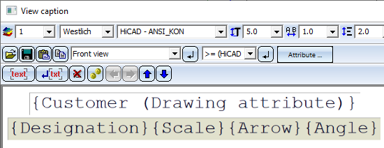
To do this, the View caption dialogue window is displayed, which is essentially the same as the annotation editor.
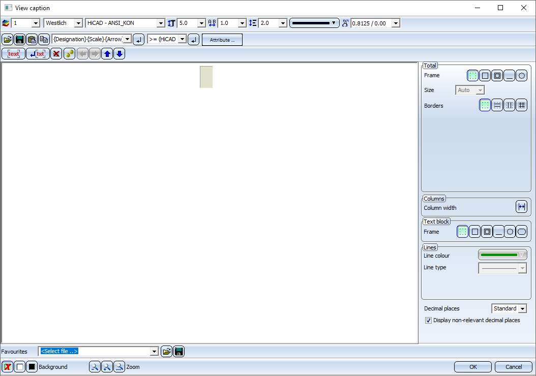
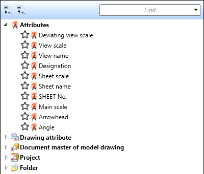
Determine the components that should be output in the caption. These can be fixed texts or attributes. For example, the view name, designation, scale and - if the view is not derived in alignment direction - arrow and angle can be transferred to the caption.
For captions in sectional views, the template file VIEWHEADER_S.FTD is available in the HiCAD SYS directory. This file can be used to configure captions in sectional views individually. By default, the FTD file is empty at first.
Example:
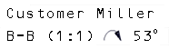
For the template file VIEWER_S.FTD, the displayed setting was saved.
In consequence, the detail view will, for example, contain the displayed caption.
![]() Please note:
Please note:
- The scale is only displayed in the caption of a sectional view if the sectional view has a different scale than the original view.
- The caption is automatically centred above the view. However, you have the option to move the caption afterwards.
Hatching
You can also display the section surfaces of a sectional view with hatchings.
To obtain a hatched display of the section surfaces, proceed as follows:
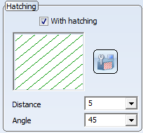
- Activate the With hatching checkbox. The current hatching setting is displayed.
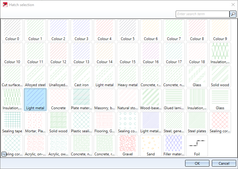
- Select a different hatch pattern if necessary. Click on the Change hatching
 icon. The Hatch selection dialogue window is displayed. If you point the cursor on one of the patterns, more information about the hatch pattern is displayed. You can also zoom the display of the patterns by clicking on the magnifying glass symbol in the lower left corner.
Select the desired pattern and confirm with OK.
- Specify the hatching line spacing and angle.
The hatching of the cut surface is influenced by the setting that has been selected for the cut surface hatching parameter in the Configuration Editor at Drawing > Views. If the Cut surface hatching parameter is set to According to material, the hatching selection in the dialogues has no effect.
Coating
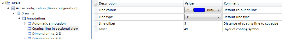
For Sheet Metal parts and Steel Engineering plates you now have the option to specify whether the coating in the sectional view is to be shown or not, by activating or deactivating the Display checkbox beneath Coating in the dialogue window. The coating is displayed in the form of an offset edge, the so-called "coating line". The settings for the representation of the coating line can be found in the Configuration Editor at Drawing > Annotations > Coating line in sectional view.
The representation of the coating line can also be changed subsequently. To do this, right-click on the coating line in the required view and choose the desired function in the Coating symbol context menu:
|
Function |
|
|---|---|
|
|
Change coating line parameters Use this function to change the colour, line type and layer of the coating line. When you call the function, the 3-D edge parameters dialogue will be displayed for this purpose. |
|
|
Change offset distance Use this function to change the offset distance, i.e. the distance between coating line and cut edge. |
|
|
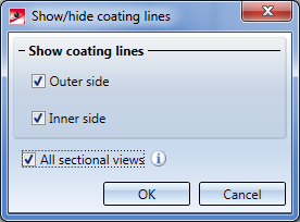
Show/hide coating lines Coating lines can be hidden or shown in the active view or in all sectional views. One distinguishes between coating lines on the inner side and the outer side. When you call the function, the following dialogue window will be displayed:
With the settings shown above, the coating lines will be shown in all sectional views on the outer side and inner side. If all coating lines have been hidden, the lines can be redisplayed again via the context menu for sheets: In the sectional view, right-click the sheet and choose Properties > Coating line. |


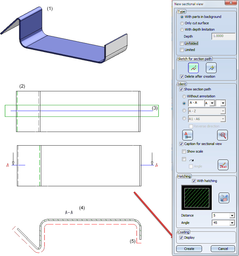
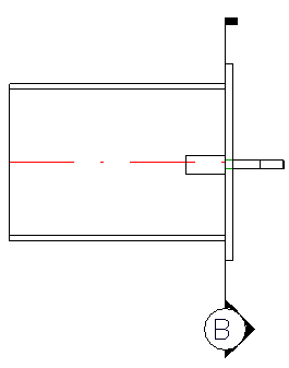
Sheet Metal part (1) with outside coating; Top view (2) with cut edge (3), Sectional view (4) with coating line (5)
![]() Please note:
Please note:
- The offset calculation for the coating lines is always carried out in the screen plane, i.e. the lines are no "fixed", permanent 3-D polylines, but will be updated upon rotation of the view.
- In dashed representations the dashing takes place segment-wise, but not over the entire length.

Special Views (3-D) • Sectional and Detail Views (3-D) • Views (3-D)