STEP

General Notes
The HiCAD interface STEP is based on the ISO standard STEP (Standard for the Exchange of Product Model Data). STEP is a tool that enables the standard-compliant data exchange between different CAD systems. STEP is mainly used to transfer the geometry data of solid models. This avoids time-consuming manual post-processing of the transferred data. Furthermore, it ensures the continuous availability of different data models from different systems in HiCAD.
In principle, HiCAD supports the subsets AP203 and AP214 with the following restrictions:
- CSG models cannot be read in.
- The STEP file should have no syntax errors if possible.
|
|
 When reading and writing STEP files you should observe the following:
 If you only want to export the active view, use the 3-D Export by views (STEP, 3D PDF...) function in the context menu of the view.
Export STEP
Drawing > Save/Print > Save as  > 3-D Formats (STEP...)
After calling the function, select the file format STEP (*.stp).
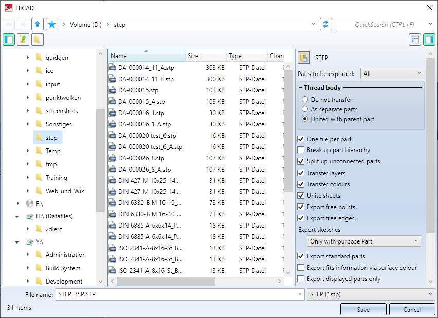
On the right side of the dialogue window you can define various options for the export. These settings can be preset in the Configuration Editor at Interfaces > General 3-D interfaces.
The parameters One file per part and Fits information via facet colour apply only to the STEP interface. The other parameters are explained in the Configuration Editor: Settings for Interfaces topic.
One file per part
If this checkbox is active (in the Configuration Editor: Parts to separate files), then each part with a geometry is exported as a separate STP file. As file name the article number of the part followed by the postfix _item number is used, e.g. DA-000014_11. If the part has no item number, then this postfix is omitted. If the part has an invalid item number, then the postfix consists only of the character _. Then each part with a geometry is exported as a separate STP file. The part structure is also saved in an STP file under the file name specified during export. This file itself does not contain any geometry but only references to the STP files of the individual parts. By exporting each part into a separate file, it is possible, for example, to edit the STEP files of individual parts. If the STP file is loaded with the corresponding part structure, the changes are then also contained in this file. This can be done for example for complex model drawings would make sense. Another application of this option is the use as a "batch export" to export certain parts to STEP format in one step.
Naming the STP files:
- The name specified during export is used for the STP file with the parts structure.
- The name of the individual part files consists of three attributes separated by _. Which attributes are used here is defined in the file brw_3dinterface.hdb in the HiCAD sys directory. The following figure shows the default setting.
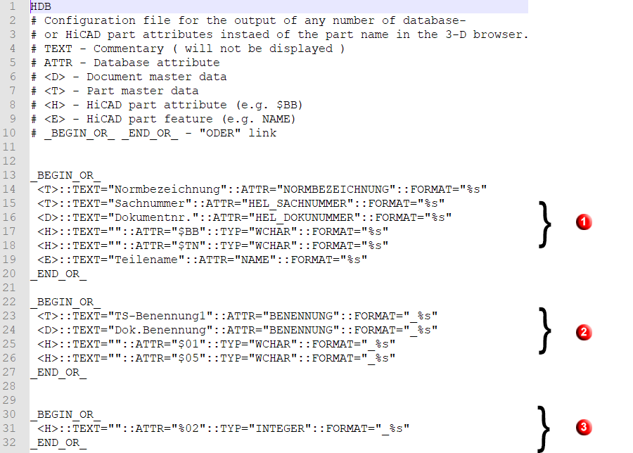
- The first component of the name is determined either by the standard description, the HELiOS article number, the document number, the HiCAD article number or the HiCAD part name. The first attribute found is used.
- The second component is either the name from the HELiOS article or document master, the HiCAD name or the part type. The first attribute found is also used here.
- The third component is the item number.
Please note that if you change this file, the configuration of the naming also affects other 3-D export formats.
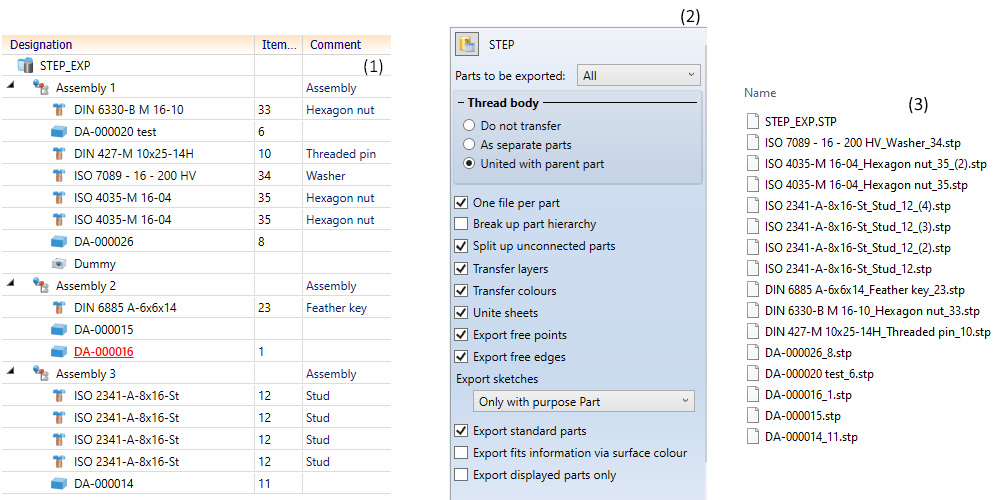
(1) HiCAD part structure, (2) Export settings, (3) created STP files
Please note the following:
If the model drawing contains identical parts, i.e. the same name, item number, etc., the STP files of these parts are given a consecutive number as an additional identification.
Only one STP file is created for referenced parts and their identical parts.
When parts are mirrored in HiCAD, this may result in "left-handed part coordinate systems". These are not supported by STEP. In this case the mirrored parts receive the name of the original part and the additional identification M (mirrored).
Tip:
If you activate this option, you should always export the files to an empty directory. Otherwise it can quickly become confusing with many parts, because already existing part files are not overwritten, but saved under the existing name followed by a continuous letter.
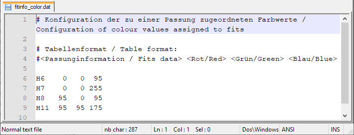
Export fits information via surface colour
Here you can specify by activating or deactivating the checkbox whether fits information are to be transferred via the surface colour. On the exported STEP part the diameter of the corresponding bore will be highlighted. For this, the option Transfer colours must be active.
In the sys directory of your HiCAD installation you will find the configuration file fitinfo_color.dat, where the assigning of RGB colour values to fits data is specified.
.
Make the desired settings and specify the path and name of the export file. When you exit the window with OK, the STEP file is generated with the settings you have made.
Import STEP
Drawing > New/Open > Open > 3-D Import 
After calling the function, first select the file type STEP file (*.stp, *.step) and then the STEP file you want to open.
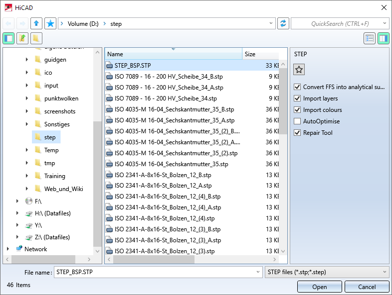
On the right side of the dialogue window you can define various options for the import. These settings can be preset in the Configuration Editor at Interfaces > General 3-D interfaces.
|
Setting |
Effect |
|---|---|
|
Convert FFS into analytical surfaces |
If this checkbox is active, free-form surfaces are automatically converted into analytical surfaces. If you do not want this, then deactivate the checkbox. This may be useful for sheet metal parts. |
|
Import layers |
These checkboxes determine whether layers and colors are taken into account during import. These settings refer exclusively to the properties of the entire part. |
|
Import colours |
|
|
AutoOptimise |
If this checkbox is active , a union of (divided) edges and surfaces is carried out directly during the import (corresponds to the HiCAD function 3D-Standard > Tools > Surface > Further ... > Optimise part). |
|
Repair Tool |
If this checkbox is active, extended correction and repair functions are automatically executed during import, which ensure a better import of "bad" STEP files. The RepairTool is a separately licensable module. If there is no valid license, the checkbox is grayed out. If necessary, you can also use your own configuration file for the RepairTool. The default system file is located in the directory of the HiCAD installation at ...\sys\CADfix\Default\Import\ and is called STEPRepair.cwc. |
Once you have made the desired settings, click on Open to start the import.
The settings made here can be saved as favourites. To do this, click on the  symbol in the dialogue. You can find more information on managing favourites in the Manage Favourites topic of the HiCAD Basics help.
You can specify which favourite is used as the default in the import dialogue in the Configuration Editor at Interfaces > Import.
![]() Please note:
Please note:
- When STEP assemblies are imported, superordinate parts in HiCAD become assemblies.
- Alternatively, you can also load STEP files via the HiCAD Start Center.

3-D Interfaces • Configuration Editor: Settings for Interfaces