Project: Steel Engineering Drawing Management (BIM-PDM)
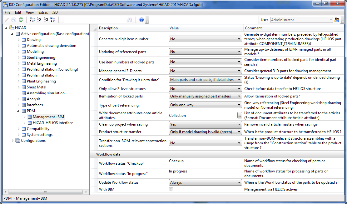
Use the Configuration Editor (ISDConfigEditor.exe in the HiCAD EXE directory) to further influence the drawing derivations via the Management+BIM module. The required settings can be found at PDM > Management+BIM.
The following parameter settings are available:
Further setting options can be found at

If you want an n-digit item number (padded with zeroes from the left) to be generated when creating production drawings, select the number of desired digits here. Possible are 2 - 6 digits.
The n-digit item number will be assigned to the HELiOS document attribute COMPONENT_ITEMNUMBER.
The default setting is No.
 The attribute COMPONENT_ITEMNUMBER can also be configured individually if required. For this purpose the template file BIM_PDM_ItemnumberGeneration.ftd is available that can be edited with the Templates, Attribute assignment
 function (Steel Engineering > Settings
  > ...).
With this parameter you can specify whether the updating of BIM-managed, referenced parts has to take place in all models. If you select Yes, HiCAD will offer you the additional function
 Update models with old referenced parts. This function enables you to update all models containing old referenced parts in one step. The default setting is No.
This parameter influences the taking into account of released (locked) parts during itemisation and identical part search.
In this way you can exclude parts that have been released (and are therefore locked against processing) from checks for equality to other parts in the drawing, and achieve that identical, but unreleased parts in the drawing will obtain a different item number.
Such cases can occur if, for example, parts have already been produced after their release, thus making further identical part search superfluous.
The default setting is No.
If you also want 3-D parts to be considered for the management of drawings, i.e. preserve the link Drawing up to date or Drawing not up to date, respectively, and use the associated SE Drawing Management automatisms, select Yes.
The default setting is No.
 Please note that general 3-D parts will not be automatically dimensioned in the drawings.
Via this parameter you can specify the way in which the "Drawing is up to date" condition will be set for drawing derivations.
The following settings are possible:
|
Main parts and sub-parts, if detail drawing created for assembly |
It is assumed that if a detail drawing creation for the assembly has taken place, detail drawings for its main parts and sub-parts also exist. |
|
Main parts, if detail drawings created for them |
The detail drawings of the main parts of an assembly are only up to date if detail drawings have been created for the main parts. |
|
Sub-parts, if detail drawings created for them |
The detail drawings of the sub-parts of an assembly are only up to date if detail drawings have been created for the main parts. |
|
Main parts and sub-parts, if detail drawings created for them |
The detail drawings of the main parts and the sub-parts of an assembly are only up to date if detail drawings have been created not only for the assembly, but also for the main parts and sub-parts. This is the default setting. This setting makes sense if, for example, if one drawing should contain only main parts, and another drawing only sub-parts. A typical use cases would be
|
The following example with an assembly, a main part and a sub-part is meant to illustrate the differences between these settings:
BIM CAD drawing
Settings for workshop drawing derivation
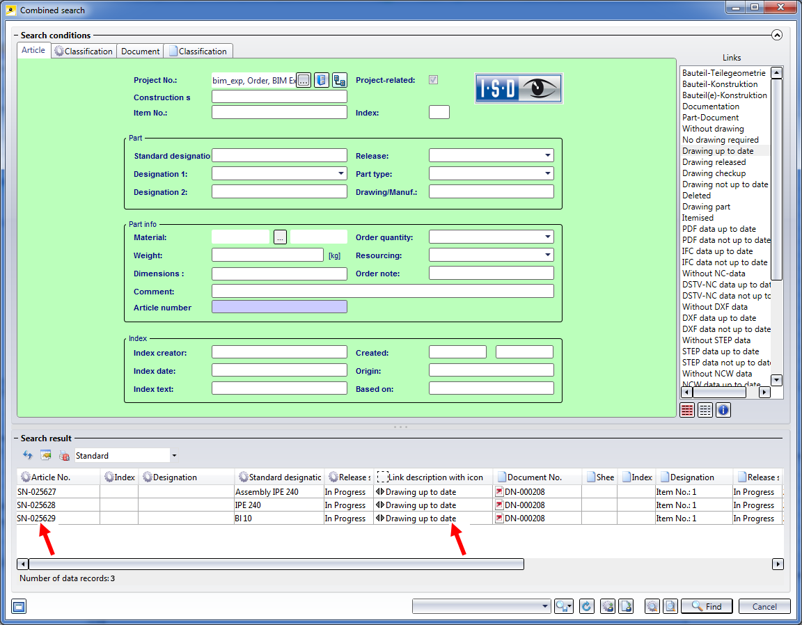
Condition for 'Drawing is up to date'= Main parts and sub-parts, if detail drawing created for assembly
If this parameter value has been chosen, the link "Drawing up to date' will not only be assigned to the detail drawing of the assembly, but also to the detail drawings of the main parts and sub-parts.
For the above example this means that the assembly, the beam and the plate will obtain the link "Drawing up to date", although a detail drawing was only generated for the assembly.
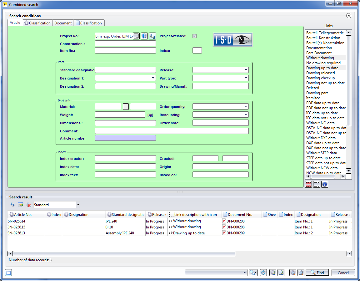
Condition for 'Drawing is up to date' = Main parts and sub-parts, if detail drawings created for them
If this parameter value has been chosen, the link "Drawing up to date" will only be assigned to the detail drawings of the main parts and sub-parts, if detail drawings have been explicitly created for them.
In the above example, however, a detail drawing was only generated for the assembly. Therefore, only the assembly will obtain the link "Drawing up to date". The beam and the plate will obtain the link "Without drawing" instead.
Please note that this setting also affects the release of drawings. For example, if you have chosen the setting Main parts and sub-parts, if detail drawings created for them, the detail drawings for the main parts and sub-parts also need to have the link "Drawing up to date". If this is not the case, an error message will be displayed.
This parameter determines the maximum depth of the part structure while using Steel Engineering Drawing Management. Default setting is no.
Example:
In the case of the 3-level part structure shown above, a saving of the drawing would only be possible with the function PDM > Drawing > Save , if the parameter Only allow 2-level structures is set to no. Otherwise the part structure would be too deep and the saving would be refused.
After the release of a drawing, the corresponding parts are normally locked against editing, which also applies to itemisation. You can use this parameter to change this. Possible settings are:
Yes
Released parts will be considered for itemisation as well.
No
Released parts will not be itemised.
Only manually... (Default)
Only parts with manually assigned article masters will be considered.
Only auto...
Only parts with automatically assigned article master will be considered.
By default, the parts of automatically generated drawings are only unilaterally referenced with the original model drawing (Only one way). This enables an automatic updating of the drawings that have been derived from the model drawing.
If you want the referencing to be bilateral, set the parameter to Normal referencing.
If desired, the document attributes of models that are managed with the Management + BIM module can be assigned to the article attributes of the parts. The assigning takes place via the String Collection Editor. Click on the  symbol in the Collection field and enter the desired assignments in the following order:
Document attribute;Article attribute
Each assignment must be defined in one line, e.g.:
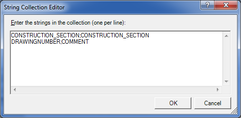
Preset here is the assignment for construction sections (aka construction units)
CONSTRUCTION_SECTION;CONSTRUCTION_SECTION
Use this parameter to determine whether invalid article masters are to be removed automatically when you save a model drawing. Invalid article masters occur as a result of part deletions.
The default setting is Yes.
If you set the parameter to No and want to remove invalid article masters subsequently, use the Clean-up ![]() function in the Project function group for this. This function cleans up the active project by searching for invalid article masters and removing them.
function in the Project function group for this. This function cleans up the active project by searching for invalid article masters and removing them.
This parameter determines the conditions for a product structure transfer to HELiOS.
|
Only if model drawing is valid (green) |
The product structure will only be transferred if the BIM model drawing is valid, that is, if a corresponding article exists in the HELiOS database for each part. A valid model drawing is marked with the This is the default setting. |
|
Upon each saving with BIM |
The product structure will be transferred each time you save with the Management + BIM module - even if the model drawing has not been completely passed on to HELiOS yet. |
HiCAD model drawings in Steel Engineering are often split into so-called construction sections, e.g. frameworks, platforms, columns, platform support structures etc. These construction sections are normally non-BOM-relevant structure assemblies. If the usages Construction section or Production section are assigned to these construction sections, they will even be transferred to the HELiOS product structure if they are not BOM-relevant. For this to happen, the parameter Transfer non-BOM-relevant construction sections in the Configuration Editor must have been set to Yes.
Also, please note that the article master of these assemblies must be created manually!
Here you specify the designation for the Workflow statuses "Checkup" and "In progress".
The following text keys have been pre-set by the ISD as follows:
|
STB_HELIOS_81 |
Checkup |
|
STB_HELIOS_82 |
In progress |
These settings concern only the Workflow, and not the identification of the release status in the title block!
Parts from released drawings and parts from drawings in "Checkup" state are marked as such in the ICN. The corresponding marking symbols are updated automatically in case of changes.
The frequency of this updating can be changed, e.g. if you want to speed up the build-up of the ICN when you are dealing with very slow connections or very large model drawings.
Possible settings are:
|
Always |
The Workflow status will always directly be updated for all parts. |
|
Always (without standard parts) |
The Workflow status will be updated for all parts except for standard parts. |
|
BIM update when saving with HELiOS |
The Workflow status will only be updated for all parts after saving. |
|
BIM update (without standard parts) when saving with HELiOS |
The Workflow status will only be updated for all parts (except for standard parts) after saving. |
The default setting is Always.
This checkbox will be automatically activated when you perform a corresponding parameter configuration. You will only have access to the functions of the Management + BIM tab if the checkbox is activated.

Requirements for a Smooth Operation (ManBIM) • Management + BIM Settings in the Configuration Editor (ManBIM) • Important Information (ManBIM)
|
© Copyright 1994-2019, ISD Software und Systeme GmbH |
 symbol in the ICN.