
Project: HiCAD Profile Installation
Derived drawings of profile installations can be adjusted in two ways: Via Adjustment of the annotation block and the Adjustment of the part annotation.
The generation of annotation blocks in drawing derivations of profile installations can be configured in the Configuration Editor at Drawing > Annotations > Profile installation dimensions. The setting options you can find there are identical to those described for the function 3-D Dimensioning + Text > Tools > Set parameters for new general dimensions.
The content of an annotation block is defined via the Configuration Editor; you find the relevant settings at Drawing > Annotations > Profile installations > Further settings > Text block contents.
The default content of the annotation block is as follows:
%COD(%U%TA($BB) x %U%TA(§25) / %U%TA($07)%U%TA(%PI))%NUM(%HID)
The "outside" portion %COD(...)%NUM(%HID) is fixed and must never be changed. The portion between the brackets can be assigned freely. Here, it reads as follows: %U%TA($BB) x %U%TA(§25) / %U%TA($07)%U%TA(%PI). %TA represents the attributes of a part ("TA" stands for German "TeileAttribute" = Part attributes). Then, the part attribute to be queried follows in brackets, i.e. %TA($BB) designates the part attribute $BB of the profile - the Article number.
In the case of profile installation we deal with the special situation that one profile in HiCAD normally consists of several parts: One part for the contour representation, one for the exact representation, and, possibly, some more parts. In this situation the part attributes are assigned to an assembly that contains the individual sub-parts. However, this means that in the drawing, not the attributes of the displayed part can be used, but the attributes of the superordinate part must be used. This is ensured via the expression %U. According to this principle, %U%TA($BB) designates the part attribute $BB of the superordinate part, i.e. the desired designation.
Static text (i.e. text that does not depend on any variables or attributes) can be directly entered.
So, the default setting for the annotation block means the following:
<Article number> x <Length for shipping> / <Material designation><Dispatch item number>
The difference between the "normal" item number and the Dispatch item number is explained here.
The number of identical profiles can be found in a special part attribute called DWF_BUNDLE_SIZE. To include this attribute into the annotation block, you need to use the following code:
%U%TA(DWF_BUNDLE_SIZE)
The complete annotation block could then look as follows:
%COD(%U%TA(DWF_BUNDLE_SIZE)x %U%TA($BB) x %U%TA(§25) / %U%TA($07)%U%TA(%PI))%NUM(%HID)
All available part attributes can be used in annotation blocks. The table below lists some attributes that are particularly useful:
$BB
|
Article number. The designations of the profiles are entered here. |
%02
|
Item number |
%PI
|
Dispatch item number |
%PIQ
|
Total number of parts with the same dispatch number (for the annotation of a block, DWF_BUNDLE_SIZE may be of more interest, as it only indicates the number of the parts in the current annotation block) |
§01
|
Weight of a profile |
§16
|
Weight per length |
§03
|
Length (means the installed length - in annotation blocks for parts that normally have different installed lengths, but identical shipped lengths, the utilization of the Shipped length §25 probable makes more sense) |
§25
|
Shipped length. Means the length of the uncut profile (i.e. before cutting the profile to the desired length, including possible length changes via the Length optimization function). |
P_TYPE
|
Usage |
$05
|
Part type |
DWF_BUNDLE_SIZE
|
Number of profile to which this annotation block applies. |
DWF_PACKAGE_NAME
|
Name of package |
This is just a selection of the part attributes that are available. You can use any attribute.
Furthermore, you can also conveniently adjust the formatting for the annotation block. To do this, open the Configuration Editor and go to Drawing > Annotations > Profile installation dimensions > Font: Auxiliary text. There you can, for instance, configure the colour and font of the annotation block.
![]() Important:
Important:
Changes to the settings for annotation blocks will only take effect after a restart of HiCAD.
Choose Drawing > Itemisation/Detailing > Edit part annotation templates. In the dialogue window beneath Usage-dependent configuration, select RW_GROUP from the list.
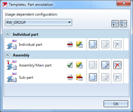
In the Assembly area of the dialogue window, the entry Assembly/Main part is used for annotating the layers. Click on the  Edit button.
The dialogue window for the annotation settings will be displayed:
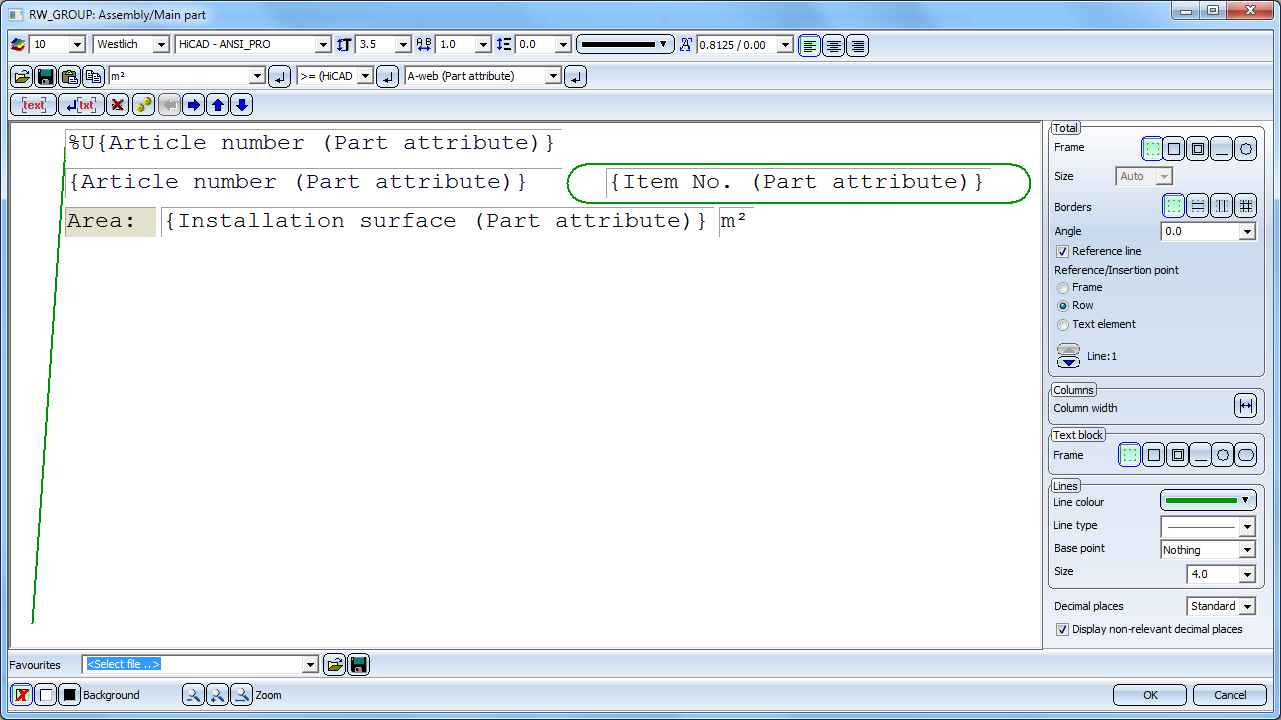
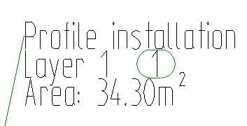
Here you can modify the annotations. The default setting creates the following annotation in derived drawings:
General information on the operation of the dialogue window can be found in the Help topic Change Annotation Settings (3-D).
![]() Please note:
Please note:
%U,not the variable of the part will be selected, but the variable of the superordinate part. The part annotation refers to a layer in the installation. This means that %U{Article number (Part attribute)} will not return the article number of the layer, but the one of the part that is superordinate to the layer - which, in profile installations, is always the Profile installation itself. So, the article number of the Profile installation is output in this way.

Profile Installation • Set-up of Drawing Derivation • Other Properties
|
© Copyright 1994-2019, ISD Software und Systeme GmbH |