Project: HiCAD Plant Engineering
The redesigned function for the automatic placing of parts on guidelines comes with a significantly increased performance.
Example 1:
Options: With weld seams, maximum pipe length 700, no connecting parts, part cache active and filled, data source: HELiOS:
|
Previously |
SP2 |
|---|---|
|
12sec |
2sec, i.e. 16% of former time |
Example 2:
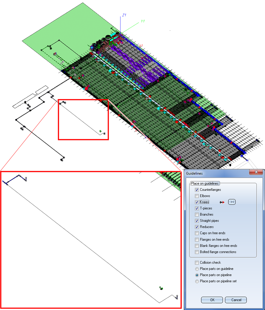
The image below shows a model drawing by the company Certhon Build B.V. (Poeldijk, The Netherlands). The highlighted section is to be occupied with parts.
Options: With weld seams, no connecting parts, part cache active and filled, data source: HELiOS:
The parts that are to be placed on the guidelines are also parts made by Certhon, with the utilized pipe class containing the following parts according to EN 10219:
|
Test |
Previously |
SP2 |
|
|---|---|---|---|
|
1 |
Maximum length for straight pipes: 10m. |
2min |
10sec, i.e. 8% of former time |
|
2 |
Maximum length for straight pipes: 1m. |
17min |
15sec, i.e. 0.5% of former time |
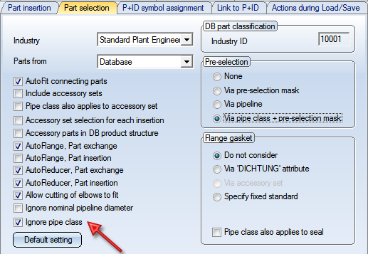
When inserting parts you have now the option to temporarily ignore the pipe class. For this purpose the Ignore pipe class checkbox has been added in the selection window for pipe parts. The default setting of this checkbox can be set on the Part selection tab of the Plant Engineering Settings dialogue window.
The choice of the pipe class takes place according to the following principle:
New on this tab is the Ignore pipe class checkbox. This checkbox determines whether or not the pipe class is to be ignored when you insert parts.
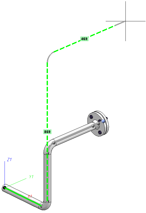
Sections the length of which have been changed by a new route will now be represented as dashed lines. Also, you have now the option to show additional information by activating the corresponding checkboxes beneath Text display in the Change route dialogue window.
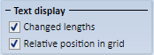
If you want to display the changed lengths as texts, activate the Changed lengths checkbox.
Relative position in grid
If the Use grid checkbox is active, the grid will be visualized by dotted lines. If the Relative position in grid is also active, the distance to the start point will be written, along the grid axes, to the auxiliary lines. To distinguish such distances from the texts for the changed lengths, they will be preceded by a capital Δ (Delta).
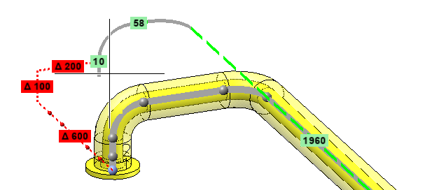
The dynamic route change is now supported by a grid. This can be useful if you want to move the connecting point of a pipe by a defined value in the direction of a connection that does not run along one of the axes of the currently active coordinate systems.
The origin of the grid will always lie in the point to be moved in the process. The orientation will be selected in such a way that one of the axes of the grid runs in connection direction, and a second axis lies in the XY-plane of the active coordinate system.
The grid is represented by dotted auxiliary lines, on which the current grid spacing is visualized by means of small spheres.
If the Relative position in grid checkbox beneath Text display has been activated in the dialogue window, the distance to the start point will be written, along the grid axes, to the auxiliary lines. To distinguish such distances from the texts with changed lengths, they will be preceded by a capital Δ (Delta).
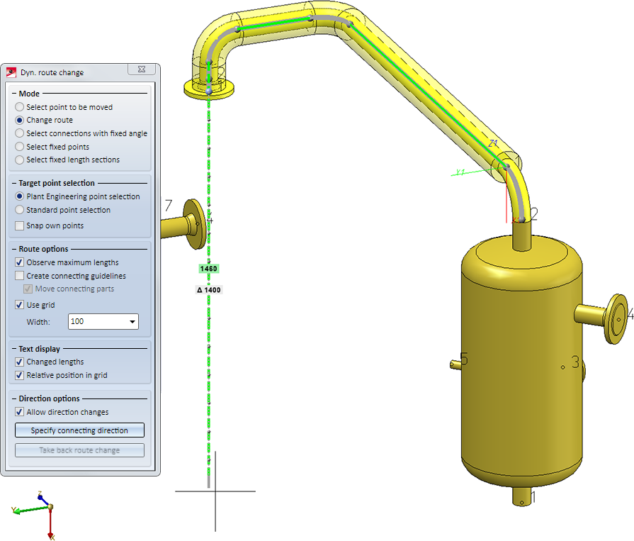
This display is particularly useful if a length change runs along a grid axis. In the image below, for instance, the short straight pipe at the end of the pipeline is lengthened in downward direction. The new length of the pipe will be 1460, while the end point of the pipeline will be moved downwards by 1400 units:
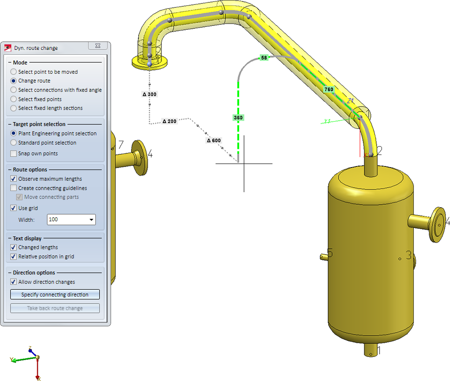
Immediately below the Use grid checkbox you can specify the incremental width (spacing) of the grid. Please note that you can also pick the grid spacing from the drawing when you have chosen Pick distance from the context menu of the input box. If the selected grid point cannot be reached with the route change, the auxiliary grid lines and the text boxes will be highlighted in red:
![]() Please note:
Please note:
New in the Assign  pull-down menu is the Collision check
  function. This function checks whether a pipeline collides with other objects of the model drawing. It does not check whether parts of the pipeline collide with each other
If a pipeline is active when you call the function, the collision check will be carried out for this pipeline. Otherwise, HiCAD asks you to choose a pipeline for which the collision check is to be carried out.
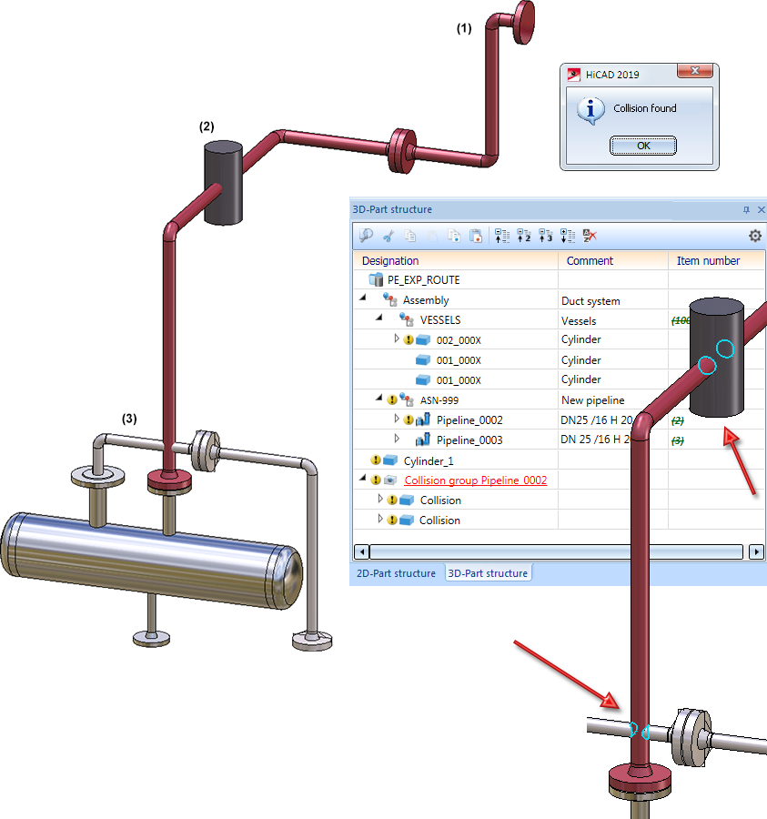
If collisions are found, an appropriate message will be displayed and HiCAD will generate so-called "collision parts" which can be found in the ICN, beneath the part Collision groups name . name is the name of the checked pipeline.
An example:
In the image below the Pipeline (1) collides with the Cylinder (2) and the Pipeline (3). If you carry out the collision check, there will be 2 collision parts in the Collision group.
The AutoPlace parts on guidelines  function has been fundamentally revised.
Detail representation for a clearer overview
If a part for a particular fitting situation needs to be found during automatic placing of parts, an appropriate search window will be shown. This search window can belong to a different application, e.g. HELiOS. If such a window is shown, HiCAD will not allow any inputs, i.e. you cannot navigate in such a situation.
In previous versions the selection of a suitable parts could sometimes be difficult, if the search request referred to an "invisible" fitting situation. In many of such situations the fitting context of the part was rather unclear.
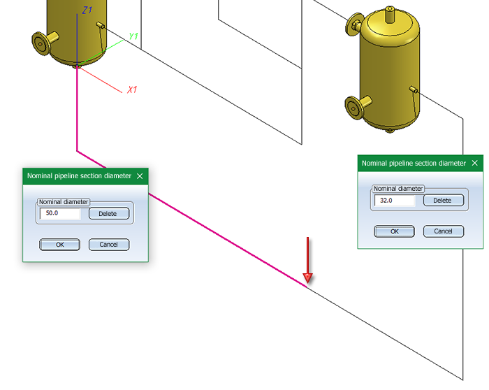
For the sake of a clearer overview, a second window with an enlarged detail view of the current fitting situation will be shown. This means that the drawing area is split into two areas during automatic part placing: On the left an overview of the complete pipeline is shown; on the right, an enlarged representation of the concrete fitting situation is shown. In both representations, an arrow pointing at the current fitting situation is displayed. The direction of the arrow corresponds to the viewing direction in the detail view.
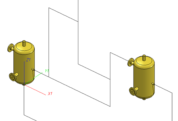
Example:
The following example shows the original drawing, where the automatic placing of parts initially sets a counterflange:
If you now start the automatic placing of parts, the following will be displayed as soon as the search window offers concrete flanges for selection:
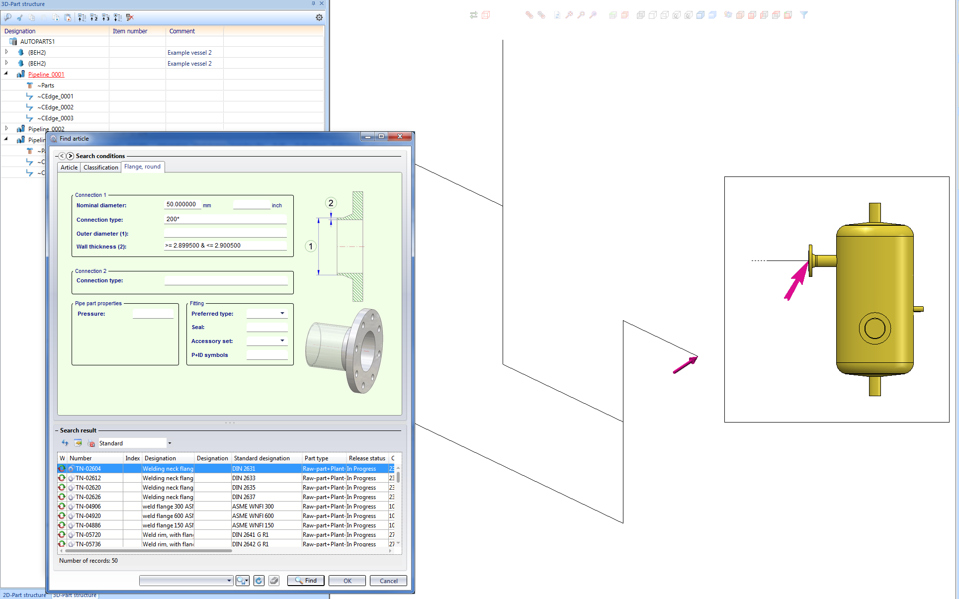
The vessel will only be displayed in the detail window, as it does not belong to the pipeline. This representation serves the purpose of a clearer overview, since vessels are normally the larger parts. In the detail view, longer parts, such as pipes and guidelines, are sometimes only implied: In the present example, a portion of the guideline is implied by means of a dashed line. This representation, too, servers the purpose of a clearer overview.
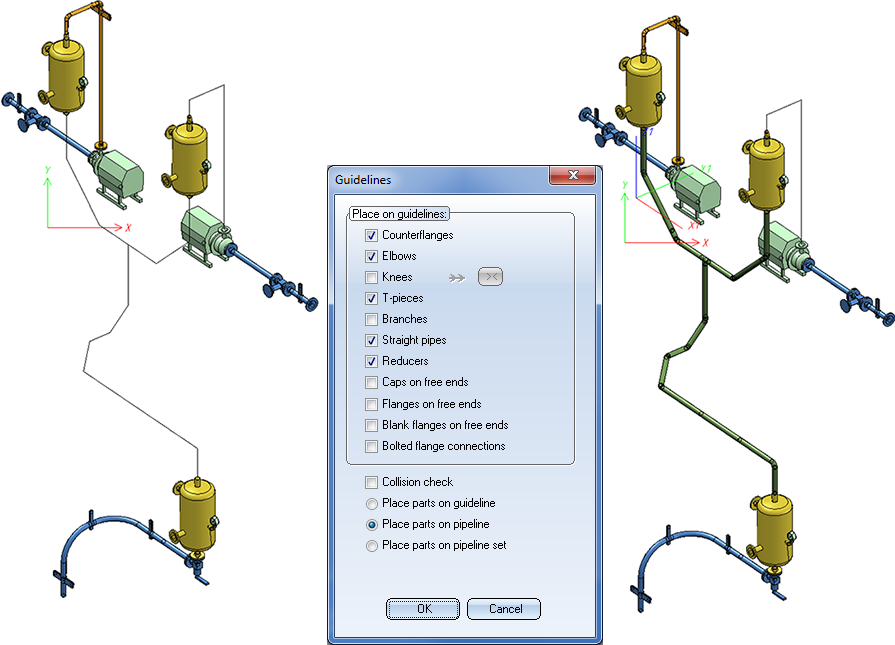
Placing of parts on pipeline sets
From SP2 onwards it is possible to interpret several connected pipelines as one pipeline set and place parts on them in one step. Use the new Place parts on pipeline set option for this.
Example:
In the image below (left), a new pipeline begins on the single flange.
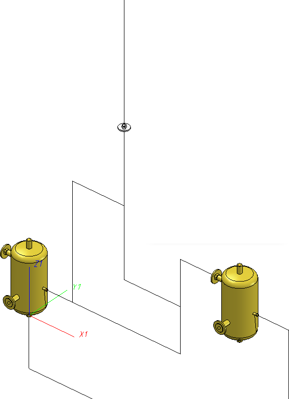
If you have chosen the Place parts on pipeline set option, parts will be placed on the pipeline set in such a way, as if the pipeline set was one single pipeline.
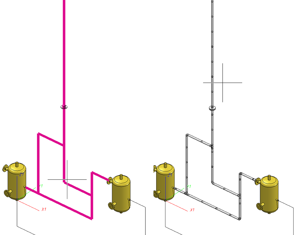
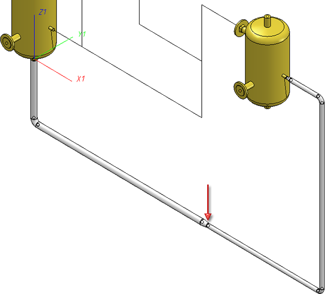
Reducers on guideline transitions
Automatic placing of parts on guidelines also supports reducers on guideline transitions. The function will then place reducers in places where there is a transition between guidelines of different nominal widths.
Such a reducer is placed midway on the transition:
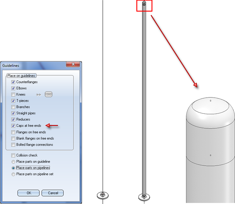
Caps on free ends
This option automatically places caps on vacant guideline ends (i.e. the start or end of a guideline). A guideline end is vacant if no part is located on the end point, and the end point is not located on the connection of a part that does not belong to the active pipeline.
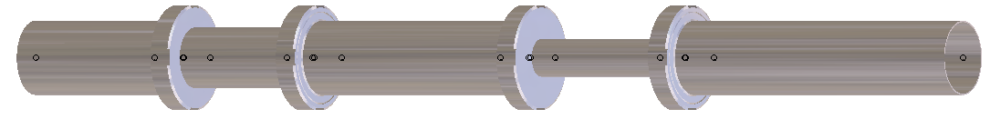
The performance for part deletion has been increased significantly. For example, a performance increase by a factor of 10 could be achieved for the model drawing shown below:
In our test the highlighted part was chosen, and the context menu function (right-click part) Delete several parts was selected, with the All parts option.
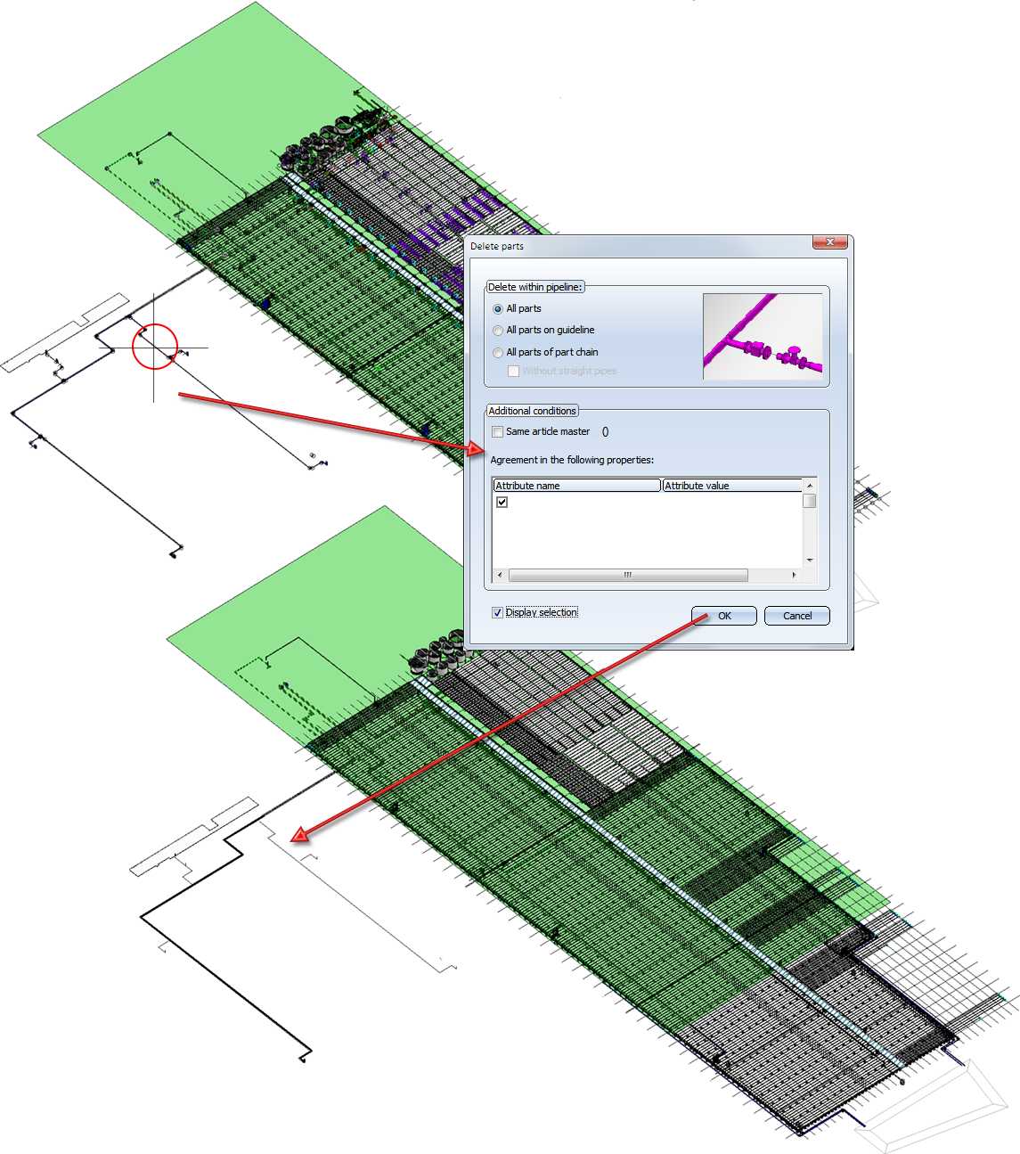
Example drawing (Certhon Build B.V., Poeldijk, The Netherlands)
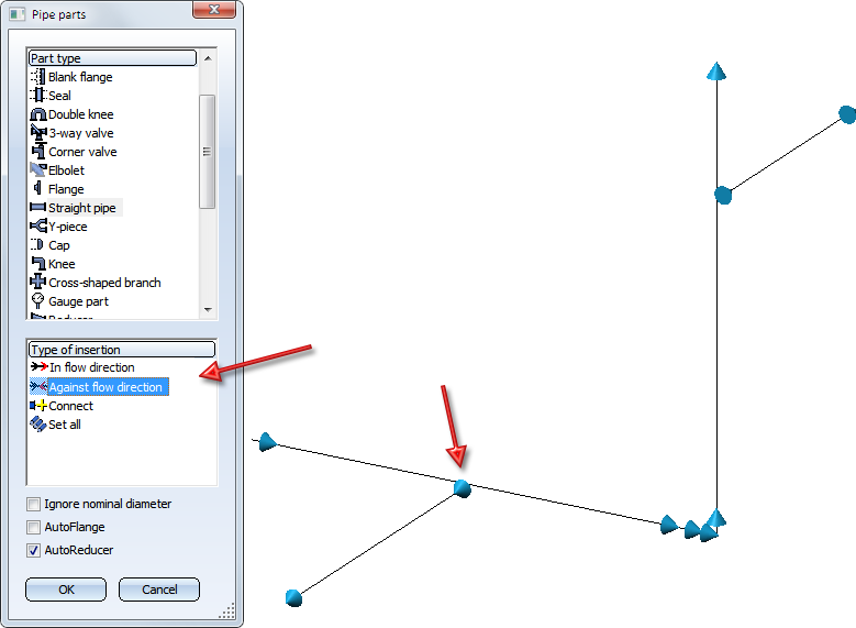
From HiCAD 2019 SP1 onwards, the flow direction (and no longer the edge direction) will be used for the determining of the orientation of parts placed onto guidelines. During part insertion, appropriate flow direction arrows will be displayed.
After insertion of a new guideline and during processing of existing guidelines HiCAD will now check whether the relevant pipeline contains a guideline on which the start point and also the end point of the new/processed guideline is located.
If this is the case, the edges that would be trimmed away will be highlighted. At the same time, an appropriate message will be displayed.
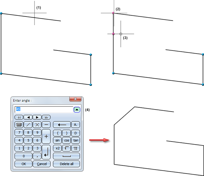
Example 1: Insertion of a new guideline
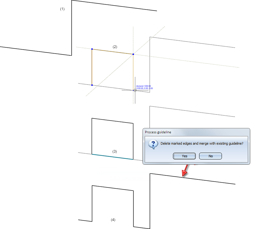
(1) Existing guideline, (2) New guideline , (3) Confirm with Yes, (4) Modified guideline
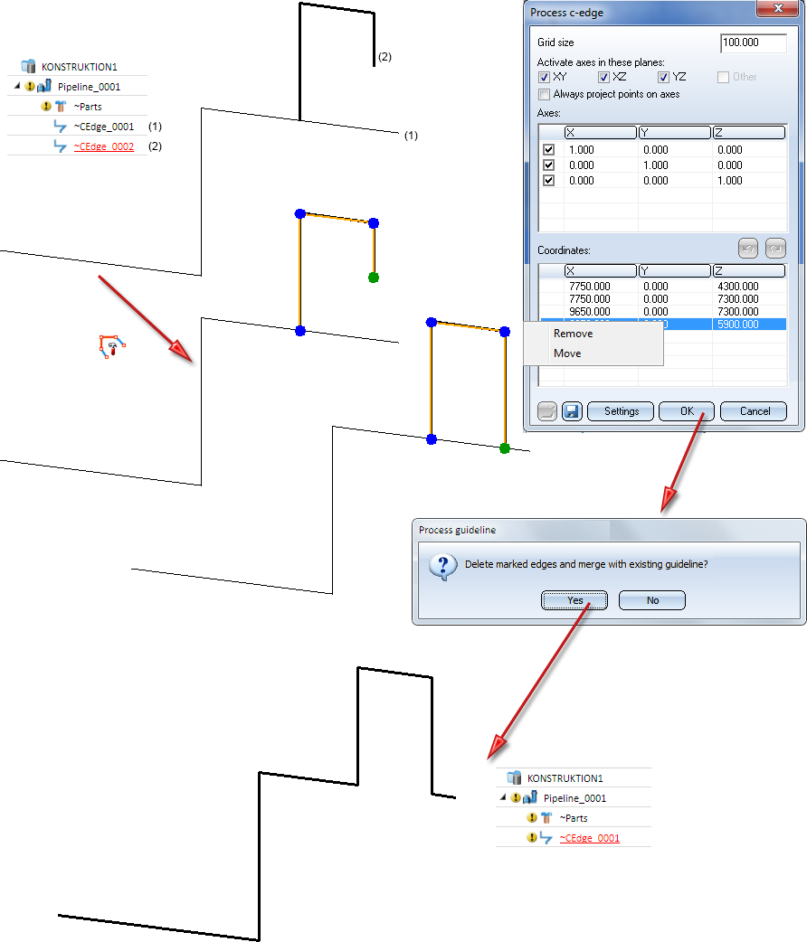
Example 2: Processing of an already existing guideline
The image below shows 2 guidelines of a pipeline. The start point of Guideline 2 lies on Guideline 1, but the end point does not. When inserting this guideline, no Trim option will therefore be offered. But if you not modify Guideline 2, moving, for example, its end point onto Guideline 1, you can trim. If you confirm the message with Yes, the highlighted edges will be removed and the two guidelines will be merged into one:
 Trimming is not possible if this would remove guidelines that already contain parts.
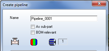
New pipelines can be marked as BOM-relevant directly during their creation by activating the new BOM-relevant checkbox.
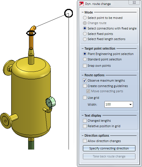
The Dynamic route change function offers a multitude of options which, however, were only active after selecting a point to be moved. In model drawings with very many connections, this could sometimes lead to confusion if the cursor had to move over a multitude of connections on its way to the dialogue window. While the Allow direction changes option was activated, unwanted route change calculations and their subsequent cancellation were often the result. The previous behaviour also made a local displacement of valve more difficult, since the fixed point required for this could only be specified after selecting the point to be moved.
Also changed has the display of connections with fixed angles. These are normally displayed by a circle with the special colour Grid (Default: Black). The circle surrounds the axis, about which the rotation would otherwise have been performed. However, there are situations where this rotation axis will only be determined after selecting the point to be moved. In such cases, connections with fixed angles will be displayed by means of a circle that lies always in the projection plane. This situation occurs, for instance, when there are bent guidelines:
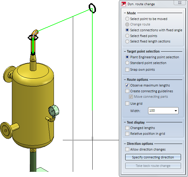
After determining the rotation axis by selecting the point to be moved, the display will be adjusted as follows:
In previous versions, when you spreaded an isometry over several sheets, one new drawing was created for each section of the pipeline (and, if HELiOS is used, a new document master was created). If an isometry was subdivided several times, things could easily get confusing.
From HiCAD 2019 SP1 onwards, only one drawing will be created for each pipeline. If a pipeline isometry is subdivided, the old isometries will be deleted, and the partial isometries will be created in the same drawing. In the process, the symbols of the isometries will be arranged into assemblies and one sheet will be created for each part isometry.
Example:
Take a look at the layout plan and its corresponding isometry shown below:
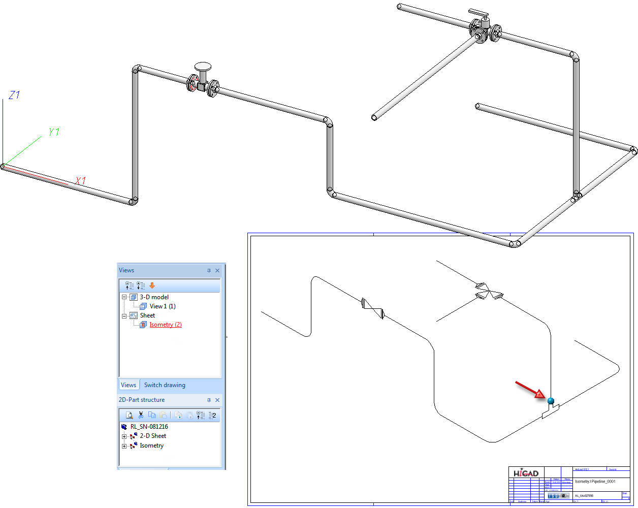
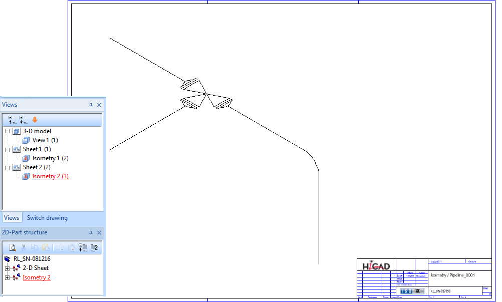
If you divide the isometry at the blue point (see red arrow) and then generate it again, the sheet with the current isometry will be deleted, and two new sheets for the partial isometries will be generated.

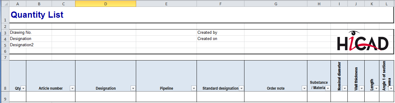
The pipeline to which a part belongs is now displayed in the Part information as well as in BOMs.
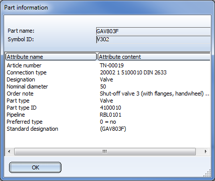
In Plant Engineering BOMs you can now find the new Pipeline (Attribute: %PipeLineName) column that indicates the pipeline to which the respective part belongs. The default template for plant Engineering BOMs, Anlagenbau_ohne_DB_SZN.rms (HiCAD sys directory) and the corresponding EXCEL template in the BOMTemplates folder have been adjusted accordingly.
Since HiCAD 2200 it has been possible to insert welded necks with loose flanges. The logic in older versions interprets the welding neck as a straight pipe to which regular loose flanges are assigned. For a placement of these loose flanges the variable F1 has been introduced, which determines the distance of the loose flange from connecting point 1 of the welding neck. However, this logic is not optimal if you want to create an isometry of the pipeline, as the flange symbol of the loose flange will then be slightly displaced.
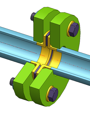
As of HiCAD 2019 SP1 you have an alternative to model such a combination of welding neck and loose flange. When using this procedure, the flanging must be of the type "Flange", while the loose flange is an asymmetrical fastener. The flange connection of the welding neck must have the connection type 20600. The 6 coming in the third place encodes the asymmetrical fastener with flange connection, i.e. normally a loose flange classified as fastener. For this procedure the variable F1 will also determine the distance of the loose flange to connecting point 1 of the welding neck. For welding necks, F1 normally equals the wall thickness.
In contrast to welding necks that are modelled as straight pipes, the flange symbol is assigned to the welding neck here. This ensures that the position of the flange symbol in a generated isometry will not be affected by a possible moving of the loose flange.
Please note:
If you want to fix the loose flange by a welding point, you should not model it as a fastener, as fasteners do not support welding points on connecting points 2. In this case you must use genuine loose flanges, i.e. such flanges that are actually classified as flanges.
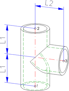
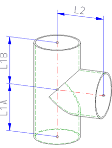
In previous versions, T-pieces were always symmetrical, i.e. the inserted pipe had always to be located in the middle between the named points 1 and 2. From now on, you can also insert asymmetrical T-pieces.
If the variable L1 exists in the variant, the insertion length will be the double amount of L1. Otherwise, the insertion length will be the sum of L1A and L1B.
|
Old |
New |
|---|---|
|
|
|
The standard part inventory has been expanded by the following parts acc. to DIN 11851:
|
Part type |
Part |
Variant |
|---|---|---|
|
Blank flange |
Threaded dummy socket |
N11851_BGS.VAA |
|
Blank flange |
Tapered dummy socket |
N11851_BKS.VAA |
|
Sealing gasket |
O-ring |
N11851_OR.VAA |
|
Double knee |
Reversal pipe bend 180° KK |
N11851_DOUBLEKNEE_KK.VAA |
|
Double knee |
Pipe bend 180° KK |
N11851_KNEE180_KK.VAA |
|
Flange |
Threaded socket |
N11851_GS.VAA |
|
Flange |
Tapered socket |
N11851_KS.VAA |
|
Straight pipe |
Intermediate piece GK |
N11851_STR_GK.VAA |
|
Straight pipe |
Intermediate piece KK |
N11851_STR_KK.VAA |
|
Straight pipe |
Intermediate piece GG |
N11851_STR_GG.VAA |
|
Knie |
Pipe bend GG |
N11851_KNEE_GG.VAA |
|
Knee |
Pipe bend GK |
N11851_KNEE_GK.VAA |
|
Knee |
Pipe bend GS |
N11851_KNEE_GS.VAA |
|
Knee |
Pipe bend KK |
N11851_KNEE_KK.VAA |
|
Knee |
Pipe bend KS |
N11851_KNEE_KS.VAA |
|
Cross |
Cross piece GGGG |
N11851_CROSS_GGGG.VAA |
|
Cross |
Cross piece KGGG |
N11851_CROSS_KGGG.VAA |
|
Cross |
Cross piece KGKG |
N11851_CROSS_KGKG.VAA |
|
Cross |
Cross piece KKKG |
N11851_CROSS_KKKG.VAA |
|
Cross |
Cross piece KKKK |
N11851_CROSS_KKKK.VAA |
|
Reducer, symm. |
Reducer GG |
N11851_RED_GG.VAA |
|
Reducer, symm. |
Reducer GK |
N11851_RED_GK.VAA |
|
Reducer, symm. |
Reducer KG |
N11851_RED_KG.VAA |
|
Reducer, symm. |
Reducer KK |
N11851_RED_KK.VAA |
|
Reducer, symm. |
Threaded reducer socket |
N11851_RGS.VAA |
|
Reducer, symm. |
Tapered reducer socket |
N11851_RKS.VAA |
|
Other pipe part |
Threaded screw-on socket |
N11851_GAS.VAA |
|
Other pipe part |
Threaded screw-in socket |
N11851_GES.VAA |
|
Other pipe part |
Tapered screw-on socket |
N11851_KAS.VAA |
|
Other pipe part |
Tapered screw-in socket |
N11851_KES.VAA |
|
Other pipe part |
Compensator GG |
N11851_KOMP_GG.VAA |
|
Other pipe part |
Compensator GK |
N11851_KOMP_GK.VAA |
|
T-piece |
T-piece GGG |
N11851_TBEND_GGG.VAA |
|
T-piece |
T-piece GGG |
N11851_TEE_GGG.VAA |
|
T-piece |
T-piece GGK |
N11851_TEE_GGK.VAA |
|
T-piece |
T-piece GKG |
N11851_TEE_GKG.VAA |
|
T-piece |
T-piece GKK |
N11851_TEE_GKK.VAA |
|
T-piece |
T-piece KKG |
N11851_TEE_KKG.VAA |
|
T-piece |
T-piece KKK |
N11851_TEE_KKK.VAA |
|
T-piece |
T-piece SGK |
N11851_TEE_SGK.VAA |
|
Fastener, asymm. |
Slotted nut |
N11851_NUT.VAA |
For an easy transfer to the database these parts are listed in the foodline11851.lst file in the PlantParts directory.
Also new are the following parts from the catalogue of the company Kieselmann:
|
Part type |
Part |
Variant |
Standard designation |
|---|---|---|---|
|
Blank flange |
Blind plug - Sheet |
KM11851_BKB.VAA |
Kieselmann 11851 |
|
Blank flange |
Tapered dummy socket |
KM11851_BKS.VAA |
Kieselmann 11851 |
|
Seal |
Sealing ring |
KM10357_OR.VAA |
Kieselmann 10357 |
|
Flange |
S-flange PN10 |
KM10357_SF_PN10A.VAA |
Kieselmann 10357 |
|
Flange |
Small flange |
KM10357_SF.VAA |
Kieselmann 10357 |
|
Flange |
Small flange, slot |
KM10357_SF_SLOT.VAA |
Kieselmann 10357 |
|
Flange |
Welding neck, DIN |
KM10357_WN_DIN.VAA |
Kieselmann 10357 |
|
Flange |
Threaded socket |
KM11851_GS_L.VAA |
Kieselmann 11851 |
|
Flange |
Tapered socket |
KM11851_KS_L.VAA |
Kieselmann 11851 |
|
Flange |
Small blank flange |
KM11853-2_BBF-2.VAA |
Kieselmann 11853 |
|
Flange |
Small blank flange 1 |
KM11853-2_BBF.VAA |
Kieselmann 11853 |
|
Flange |
Clamped welded fusion spigot |
KM32676_CSS.VAA |
Kieselmann 32676 |
|
Reducer, symm. |
Reducer, concentric |
KM11852_RK.VAA |
Kieselmann 11852 |
|
Reducer, asymm. |
Reducer, excentric |
KM11852_RE.VAA |
Kieselmann 11852 |
|
Fastener, asymm. |
Slotted nut |
KM11851_NUT.VAA |
Kieselmann 11851 |
These parts can be found in the list file foodline_kieselmann.lst.
With the variants KM10357_WN_DIN.VAA and ROFI10357_WN_ISO.VAA, two part families have been added to the standard part inventory that, although classified as flanges, are in fact welding necks. In total, the following welding neck variants are available:
|
Variant |
Standard designation |
|
|---|---|---|
|
KM10357_WN_DIN.VAA |
Kieselmann 10357 |
|
|
ROFI10357_WN_ISO.VAA |
RO-FI 10357 |
Contains all sub-types of the modelled welding neck |
|
ROFI10357_WN_ISO_R1.VAA |
RO-FI 10357 R1 |
Each variant contains a portion of the sub-types from ROFI10357_WN_ISO.VAA |
|
ROFI10357_WN_ISO_R2.VAA |
RO-FI 10357 R2 |
|
The variants refer with regard to their connection type to the new loose flanges of the standard DIN 2642, which are classified as asymmetrical fasteners:
|
Series |
Variant |
Standard designation |
|---|---|---|
|
1 |
N2642_LF_R1.VAA |
N2642 R1 |
|
2 |
N2642_LF_R2.VAA |
N2642 R2 |
The loose flanges of Series1 match the Variant ROFI10357_WN_ISO_R1.VAA. The loose flanges of Series 2 match the Variants ROFI10357_WN_ISO_R2.VAA und KM10357_WN_DIN.VAA.
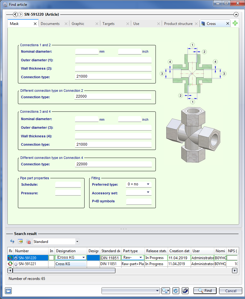
Previously, the HiCAD standard parts inventory only contained such parts with 4 connections that had identical third and fourth connections. HiCAD 2019 SP1 offers new cross-pieces ("Crosses") for which this is different. Therefore, the following system attributes have been added:
|
CNT4 |
Connection type 4 |
|
DA4 |
Outer diameter 4 |
|
DN4 |
Nominal diameter 4 |
|
DNI4 |
NPS inch 4 |
|
WTH4 |
Wall thickness 4 |
The corresponding attributes are available in HELiOS. To assign these attributes to those of the HiCAD catalogue, the following system files in the HiCAD folder PlantParts/CatSearch have been expanded accordingly:
|
File |
Expansion |
|---|---|
|
3110010.CatSearchAtt.txt |
ANSCHLUSSART2 |
|
4300010.CatSearchAtt.txt |
ANSCHLUSSART2 |
|
3300010.CatSearchAtt.txt |
ANSCHLUSSART2 und ANSCHLUSSART4 |
|
4400010.CatSearchAtt.txt |
ANSCHLUSSART2 und ANSCHLUSSART4 |
When preparing a HELiOS database for Plant Engineering tasks with the DBPlantDataImport tool, the following additional attributes will be created for a better support of parts with 4 connections:
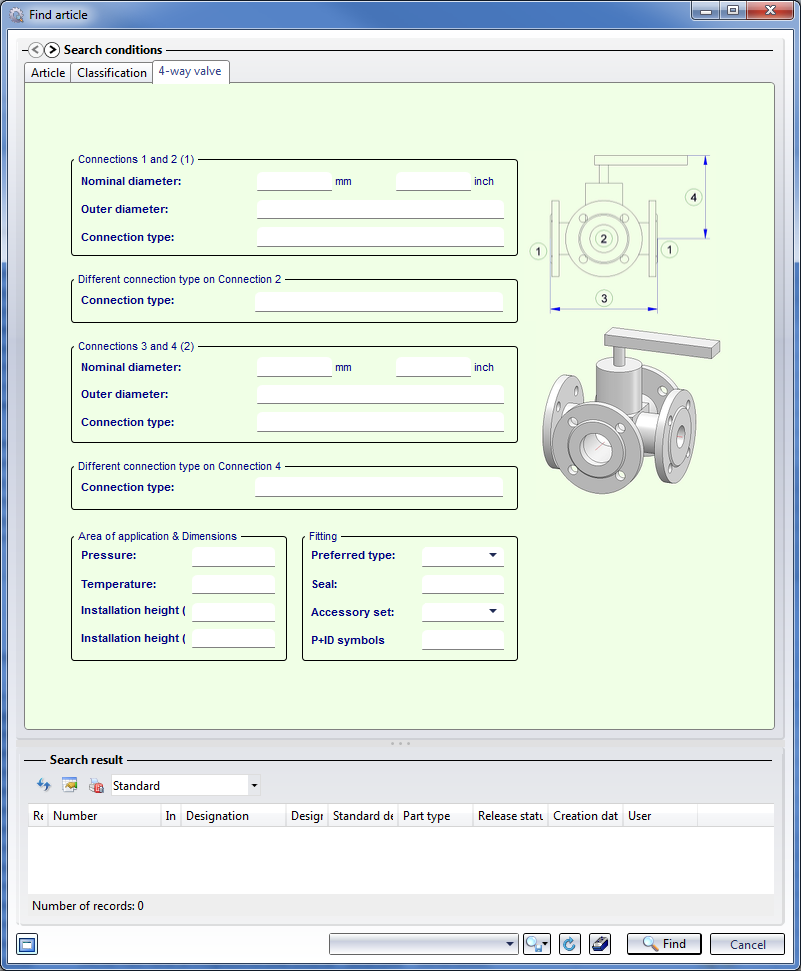
The new parts acc. to DIN 11851 for food ducts used in the food industry include crosses and valves the connection types for Connections 3 and 4 differ from each other. From HiCAD 2019 SP1 onwards, the HELiOS search masks will therefore contain corresponding new input fields, so that separate input fields now exist for deviating connection types for the Connections 2 and 4.
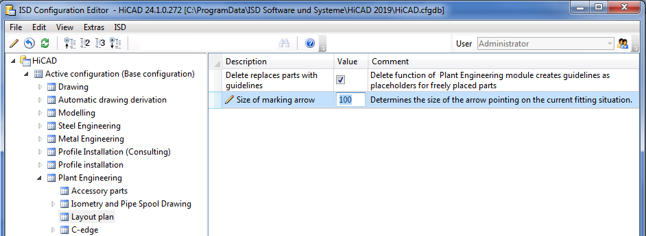
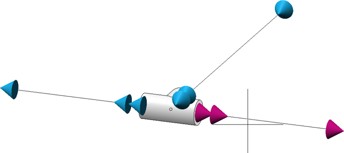
For various functions, e.g. the automatic placing of parts onto guidelines or the exchanging of parts on guidelines, an arrow pointing on the currently processed part or guideline will be displayed. The representation of the marking arrow has been changed in HiCAD 2019 SP1.
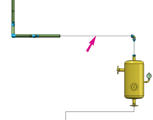
Also, the size of that arrow can be specified in the Configuration Editor at Plant Engineering > Layout plan. The value must be between 10 and 300 pixels, the default value is 80.
From HiCAD 2019 SP1 onwards, you can also change the part type ID, and thus also the classification of a VAA and a PAA file when automatically deriving variants.
The attribute assignment file (attribute_assignment.csv) supports the pseudo attribute VAREDIT_KEEP_DB_IDS for this purpose.
If this attribute has the value 1, the previous HELiOS IDs will be preserved during automatic deriving. i.e. no "actual" deriving takes place. From a HELiOS perspective, the resulting VAA or PAA file refers to the same parts. This is helpful for the adjustment of existing VAAs or PAAS, especially in conjunction with VAREDIT_MOVE_ON_SUCCESS.
Also, it is now possible to map the attribute ARTSCHLUESSEL (Type key) to a column in the file customer_list.csv. In this column the part type ID of the VAA or PAA file must then exist in the format AAAAA_BBBBBBB, with AAAAA being the coding for the industry according to anbtlken_top.dat and BBBBBBB the ID according to anbtlken.dat.
If the format should not be correct, the message
Classification not in the format AAAAA_BBBBBBB, with A = Industry and B = ID
will be issued in the output column.
If you use the PartDataAutoSync.exe tool for part data synchronization with the HELiOS database, you can now check whether the part type ID of a VAA or PAA file has changed. If this is the case, the classification of the article masters in HELiOS will be adjusted accordingly.
The Cut off corner  function has been revised completely. As of HiCAD 2019 the identification of the cut takes place in 4 steps:
During selection of the corner point or the leg start, respectively, you can go back to the previous selection step via the corresponding context menu function. When determining the angle, this happens by entering an empty angle.
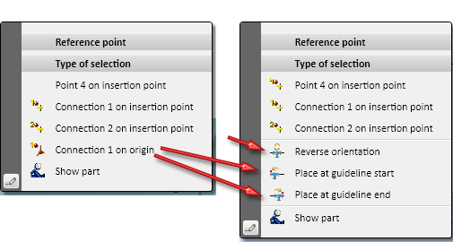
In previous versions the insertion direction of pipe parts on guidelines - In edge direction or In opposite edge direction - needed to be specified during part selection: After part selection the direction could not be changed any more. As of HiCAD 2019 it is possible to change the insertion direction of a part during its placing in the drawing. For this purpose the new Reverse orientation  function has been added to the Reference point context menu.
In addition, the part can now also be placed directly at the start or the end of a guideline. For this purpose the previous option Connection 1 on origin has been replaced with the options
 Place at guideline start and
 Place at guideline edge
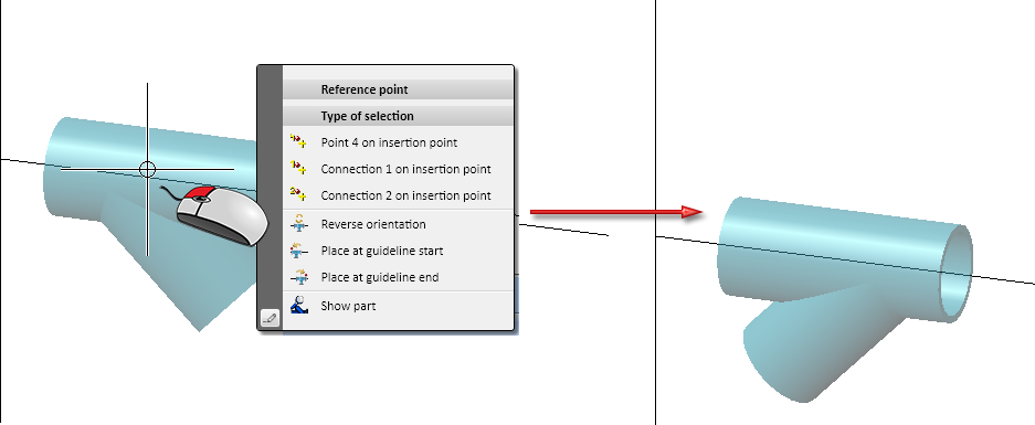
The Reference point menu can be opened with a right-click whenever HiCAD requests the fitting point specification in the drawing.
The new options are also available during exchanging of parts.
The dialogue for rotating of parts after their insertion has been revised. Up to HiCAD 2018 you could only select one connection number here. As of HiCAD 2019 rotation axis and rotation direction will be graphically visualized and the rotation axis can be freely selected.
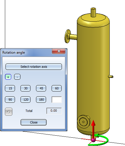
This is also true for the rotating and exchanging of parts.
The functionality of the UNDO button in the Rotation angle menu has been enhanced. Previously, the angles had been added here and then, all rotations were revoked with one UNDO action. In some situations this had led to errors, e.g. in situations where a part was first rotated, then the connecting point was changed and, finally, the part was rotated again. As of HiCAD 2019, the UNDO button revokes the rotation about the last selected rotation axis. If the rotation is 0°, the last change of the rotation axis will be revoked. In this way, it is possible to revoke several axis changes and several rotations independently from each other.
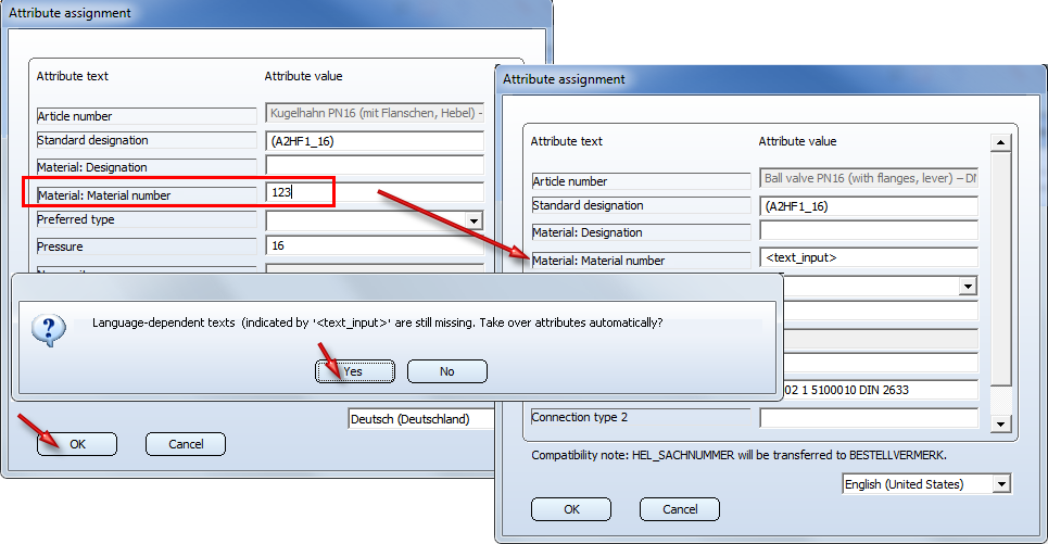
If you have used the PAA Editor or the VarToCat tool in HiCAD 2018 (or older versions) to change attribute assignments and confirmed them with OK without adjusting the attributes in all languages, the corresponding Editor issued a warning, and entered the text <text_input> into the concerned input fields.
As of HiCAD 2019, changed attribute assignments can be automatically taken over into the other languages. If attributes are missing, the following message will be displayed:
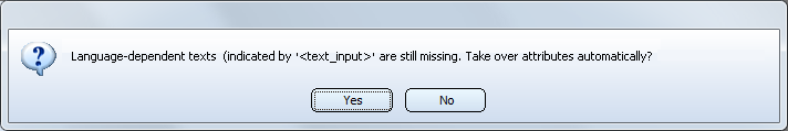
If you choose Yes, the attribute from the first language, in which has a value, will be transferred to the corresponding fields of the other language, if these are empty; otherwise, the current content of the field will remain unchanged.
If you choose No, the text <text_input> will be entered in the corresponding fields of the other languages.
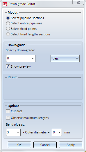
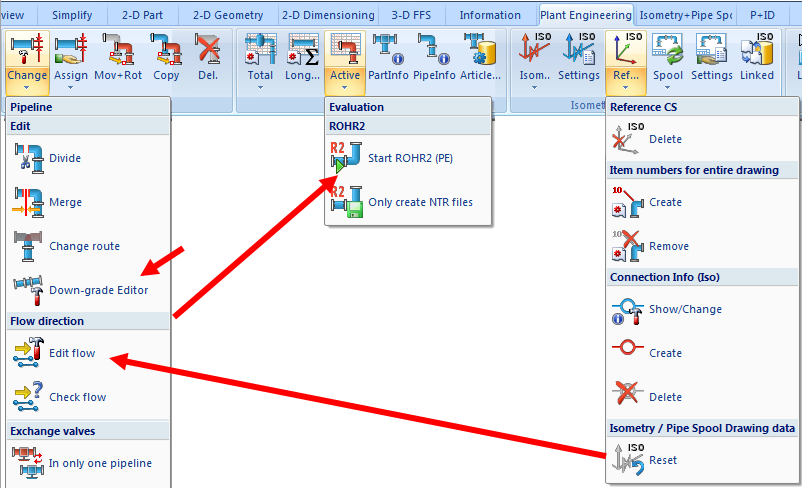
With the new Down-grade Editor  you can assign down-grades to individual sections of a pipeline. You find the Down-grade Editor at Plant Engineering > Pipeline Tools > Change > .... The Down-grade Editor works according to the following principles:
When you choose the function the Down-grade Editor dialogue window will be displayed:
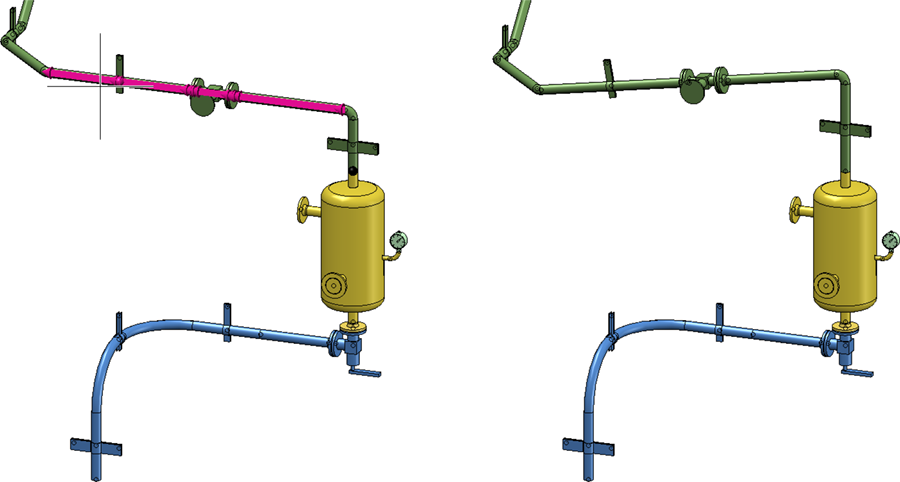
The new Down-grade Editor refers to the flow direction when assigning down-grades, i.e. as of HiCAD 2019 the relevance of the flow direction concerns not just isometries. The functions
 Edit flow and
have therefore been moved from the menu Plant Engineering > Isometry / Pipe Spool Drawing > Ref. > ... to the menu Plant Engineering > Pipeline Tools > Change > ....
Also, the functions
 Start ROHR2 and
 Only create NTR file
from the menu Plant Engineering Pipeline Tools > Change > ... have been moved to the menu Plant Engineering > Evaluation > Active > ....
In previous versions the Flow Editor could only be used to assign flows to parts. From HiCAD 2019 onwards the Flow Editor can also be used on guidelines.
If Plant Engineering variants with existing HELiOS article masters are to be used, you had only the option to enter a matching HELiOS URL for each sub-type directly during part synchronization. On the one hand, this procedure is very tiresome, and on the other hand, it requires at least the explicit permission to create article masters in HELiOS. Especially the latter may be problematic in configurations where HELiOS obtains the article masters downstream from other ERP systems. To support such cases, the mechanism for automatic variant derivation has been enhanced.
To transfer VAA files to HELiOS that were generated with the new mechanism, the tool DBPlantDataImport.exe must be called with the parameter /X. This will enable you to adjust existing article masters in a Plant Engineering compliant manner.
Further information on this procedure can be found in the Online Help of the Variant Editor, in the topic Automatic Creation of Derived Variants.
On the P+ID attribute assignment tab of the Plant Engineering Settings  dialogue window you can assign P+ID dialogue types to Plant Engineering attributes.
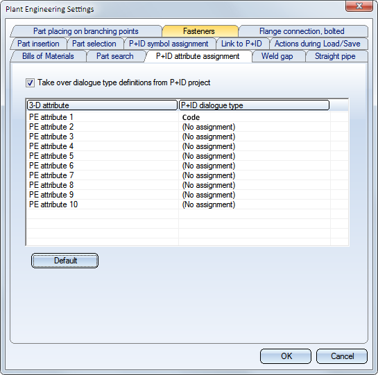
When you change one of the assigned dialogue types for a symbol in a P+ID, and then switch to the 3-D layout plan via P+ID > Link to 3-D > Assigned 3-D layout plan  , the new value of the dialogue field will be applied to the attributes of the part.
Example: Let us assume that you choose the dialogue type Code for the Plant Engineering attribute 1 and, in the P+ID, change the Code for a Vessel symbol from B1 to B2. When switching to the 3-D layout plan, the PE attribute 1 will be changed for the affected Vessel from B1 to B2. This will also be confirmed by a corresponding info message.

Plant Engineering and Pipeline Isometry
|
© Copyright 1994-2019, ISD Software und Systeme GmbH |