"Civil Engineering functions" docking window > Steel Engineering > Connections
Input fields and tabs of the dialogue window for connections depend on the function you selected. All dialogue windows are however operated in more or less the same way. The descriptions below apply to the following Design Variants:
The topics described below are as follows:
Configurations of design variants can be saved, enabling you to access your individual, customised configurations at any time. The configurations are saved as XML files to the Windows folder C:\Users\name\AppData\Roaming\ISD Software und Systeme\HiCAD nnnn\GUI\DV. (nnnn = Number of HiCAD version, e.g. 2015, name=User name).
The configuration Default has been predefined by the ISD and is initially displayed in the dialogue window under Configuration.
The following functions for configuration management are available:
|
|
Renames the current configuration |
|
|
Saves the configuration |
|
|
Saves the configuration under a different name |
|
|
Deletes the configuration |
|
|
Resets input fields to the last saved state of the configuration. |
|
|
Indicates that the current configuration has been changed, but has not been saved yet. |
|
|
Indicates an incorrect entry. |
To load a configuration, simply select it from the list box.
To create a new configuration, load an existing configuration, save it with a different name and apply the desired changes to this copy.
 Please note:
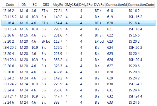
The standardised steel engineering connections according to DSTV/DAST are available in HiCAD in the form of tables. For some connections, the data for the corresponding parts (angles, plates, bolts, screws etc.) can be taken from these tables.
The desired connection can be selected in the Standard connections area.

Clicking the  icon displays all table data available for this connection.

Select the desired entry and exit the window with OK.
The designation of the selected DAST connection is displayed in the Code field.
The fields of the dialogue window, e.g. the data for the plate or the bolting, will automatically be filled with the values from the DAST table. If you change these values, HiCAD will always check whether the connection will still be DAST compatible after the changes.
The validation serves the purpose of checking the parameters when a Design Variant is fitted.

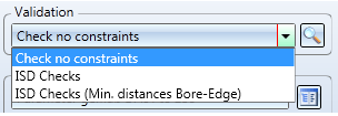
Various pre-defined checks are already available in HiCAD. These can be arbitrarily expanded if desired:
The parameters will not be checked.
The checks pre-defined by the ISD will be performed.
The bore-distance checks pre-defined by the ISD will be performed.
The check can be performed manually, by clicking the  icon. When exiting the dialogue window with OK, the check will be performed automatically.
Example:
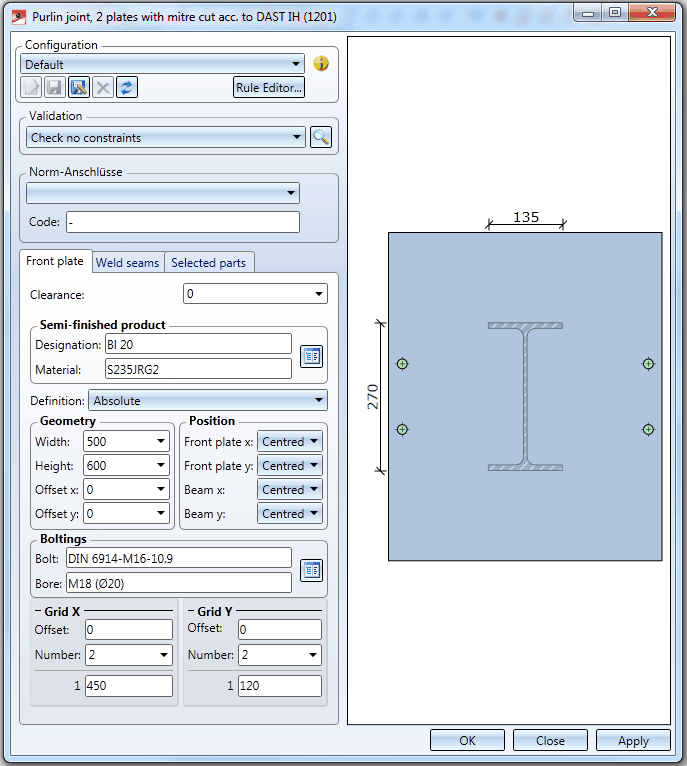
In the dialogue below, the distance of the bores to the beam edge is not recommendable from a technical point of view:

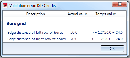
The validation will therefore produce the following result:

You specify in the XML file DV_STE_Variante_CONSTRAINTS for the corresponding variant which checks will be offered for selection. Variante stands for the designation of the variant, e.g. DV_STE_1201_00_RIDGEJOINT_CONSTRAINTS.XML for the ridge joint 1201. The file is located in the HiCAD subdirectory MAKROST3D.
To each check belongs a corresponding Python script (the format has been selected for performance reasons). These scripts use the .NET API of the ISD. Changes to the XML files and the scripts, as well as the definition of new scripts should only be made by users with appropriate knowledge.

Connections Based on Design Variants (3-D SE) • Insert Connections - Procedure (3-D SE)
|
© Copyright 1994-2018, ISD Software und Systeme GmbH |