"Civil Engineering functions" docking window > Steel Engineering > Connections > Front side to web/flange side > Front plate > Beam to web with 2 plates + stiffener (1211)
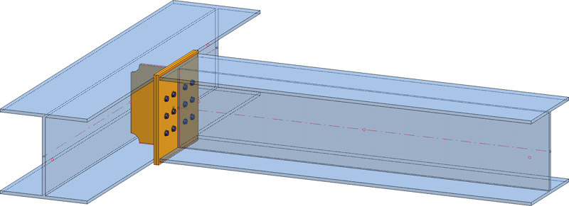
Use this function to connect two beams by means of two plates and - if desired - a stiffener. The lengthened axes of the two beams must intersect.
The Beam to web with 2 plates + stiffener (1211) dialogue window will be displayed.
The configuration of the angle connection takes place via the tabs of the dialogue window.
Click the Preview button to display a preview of the connection, based on the current data. If you want to correct the data, make the desired modifications and click Preview again to update the preview. Click OK to insert the connection with the specified data, and the dialogue window will be closed. Click Cancel to close the dialogue window without inserting/changing the connection.
Symbols:
|
|
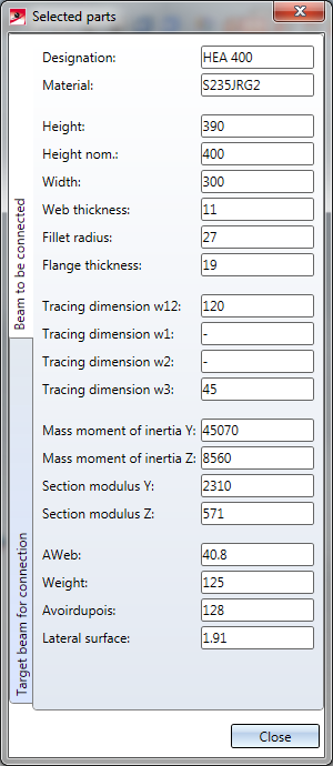
Selected parts Click on this symbol to show information on the previously identified beams, such as the type of the beam, the material, the dimensions, etc. Value inputs and changes are not possible here.
|
|
|
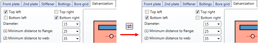
Invert concerned connection values horizontally Click on this symbol to switch specified values horizontally, i.e. right and left. For instance, this can be done for
|
|
|
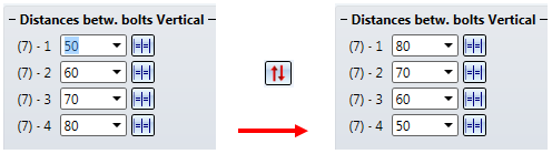
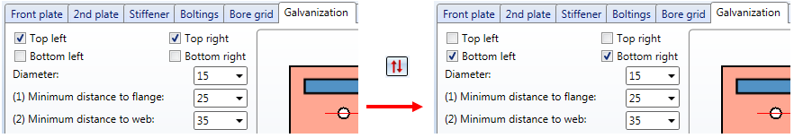
Invert concerned connection values vertically Click on this symbol to switch specified values vertically, i.e. top and bottom. For instance, this can be done for
|
![]() Please note:
Please note:

Configurations for girder connections can be saved, enabling you to access your individual, customised configuration at any time.
The configuration is configured via the settings on the following tabs:
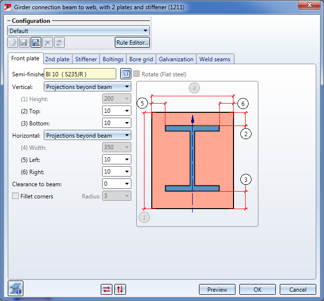
Here you specify the parameters for the front plate. This is the plate at the reference end of the beam to be connected.
The front plate on the beam to be connected can be mounted flush (Projection = 0) or with projections at the top, bottom or the sides.
|
Semi-finished products |
Click the |
|
|
|
The values beneath Vertical and Horizontal determine the height and width of the plate and its projection. 4 different procedures are available: |
|
|
Vertical |
|
|
|
Horizontal |
|
|
|
Clearance to beam |
If desired, enter a value for the clearance, i.e. the distance between the plate and the beam to be connected. |
|
|
Fillet corners |
Depending on the type of the selected semi-finished product, e.g. for plates, you have the option to Fillet corners by activating the same-named checkbox and entering the fillet radius. |
|
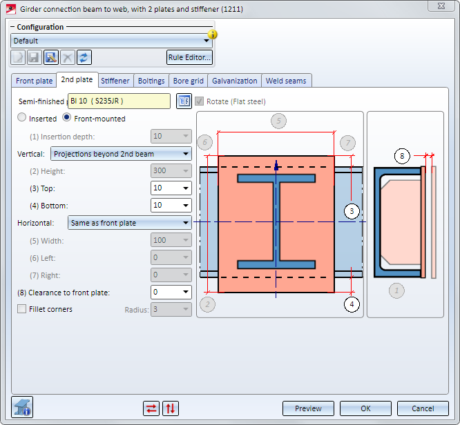
Here, you specify the parameters for the second plate. This is the plate on the target beam to which the connection is to be made.
|
Semi-finished product |
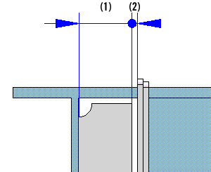
Click the The plate can be Inserted or Front-mounted. Select the desired fitting mode by activating the corresponding radio button. If you choose Inserted, please also specify an Insertion depth.
Left: 2nd plate, inserted; Right: 2nd plate, front-mounted- (1) Projection beyond 2nd beam, to, (2) Projection to 2nd beam, bottom |
|
| Vertical |
The values beneath Vertical and Horizontal determine the height and width of the plate and its projection. The following, different procedures are available:
|
|
| Horizontal |
|
|
|
Clearance to front plate |
If desired, enter a value for the clearance, i.e. the distance between the second plate to the front plate. |
|
| Fillet corners | Depending on the type of the selected semi-finished product, e.g. for plates, you have the option to Fillet corners by activating the same-named checkbox and entering the fillet radius. | |
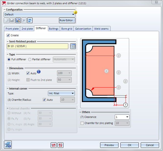
The connection can be created with or without stiffeners.
If you want to insert a stiffener, activate the Create checkbox, and click the  icon to select the type of the stiffener from the catalogue.
Further parameters are as follows:
|
Type |
Activate the corresponding radio button to specify whether you want to insert a full stiffener or a partial stiffener. |
|
Dimensions |
Full stiffener: Specify the width of the stiffener, or activate the
(2) Clearance, (1) Automatically calculated width
Partial stiffener: Specify the width of the stiffener, or activate the Specify the height of the stiffener or activate the Flush to 2nd plate checkbox. |
|
Internal corner |
Here you specify the data for the internal corner. Depending on the selected corner option, these refer to the chamfer length or the fillet radius. If you want HiCAD to automatically determine the value, activate the |
|
External chamfer |
Here you specify the data for the external chamfer for partial stiffeners. Enter, depending on the selected option, the values for chamfer lengths and chamfer angles. |
|
Others |
Enter a value for the Clearance, if desired. If you want a Chamfer for zinc plating to be created, activate the same-named checkbox.
|
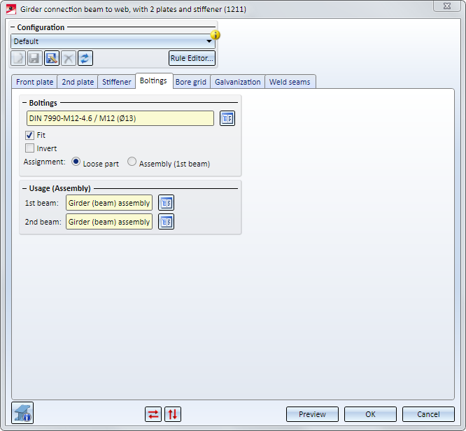
Here you specify the bolting, i.e. the bolt type, diameter etc. Click on the icon and select the components of the bolting.
Proceed in the same way as you would do with the Steel Engineering Bolting function.
The bolting will only be inserted if the Fit checkbox has been activated.
If you want to Invert the direction of the bolting, activate the same-named checkbox.
The bolting is inserted as a Bolting group. Next to Assignment you can specify whether this Bolting is to be assigned to the assembly of the 1st beam or whether it is to be inserted as a "Loose part". If you choose the "Loose part" option, the Bolting group will be inserted as a separate assembly on the same level as the assembly of the 1st beam.
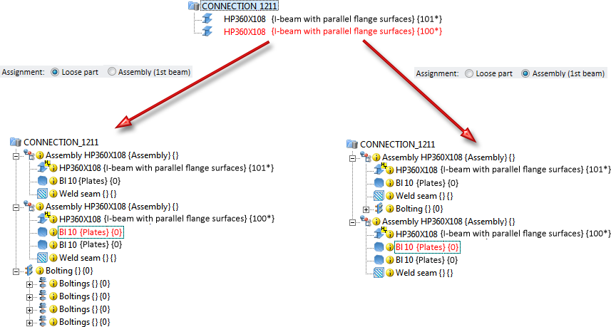
For the assemblies created during insertion of the connection, you can also specify the usage here - separately for the 1st beam to be connected and the 2nd target beam to which the connection is to be made.
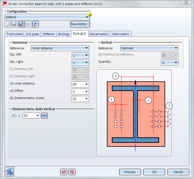
The bore grid determines the arrangement of the bore pattern for the front plate.
For both the Horizontal and the Vertical settings you first need to select a Reference first. Further settings depend on the selected reference.
|
Horizontal, Reference |
Input data |
|
Distances to plate edge (of front plate) |
|
|
Internal distance
|
|
|
Distances to web |
|
|
Vertical, Reference |
Input data |
|
Centred |
|
|
Top edge 1st beam |
|
|
Front plate, top |
|
|
Bottom edge 1st beam |
|
|
Front plate, bottom |
|
|
You can use different vertical distances between the bores if desired. If you want to all bores to have the same distance, you can simplify the input by entering a distance value in one of the input fields and clicking the clicking on the All distances equal |
|
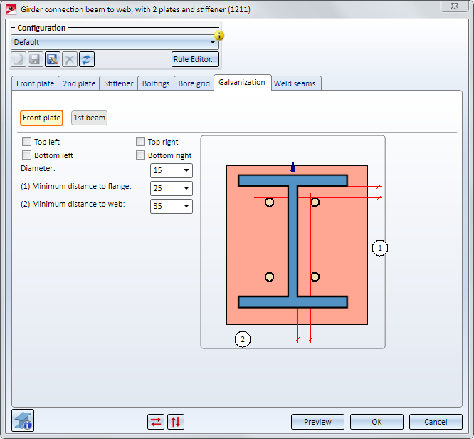
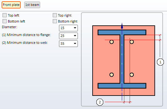
Here you specify whether the front plate should have bores for zinc plating processes. Activate the corresponding checkboxes for the bores and enter the desired diameter. Furthermore, you can specify minimum distances to flange and web.
Settings for the front plate
Determine where holes should be integrated by activating the respective checkbox and enter the requested diameter. In addition, you can enter the minimum distance of holes to flange and web.
Settings for the 1st beam
Here, you can choose via the checkbox Edit if either holes or web cuts should be integrated.
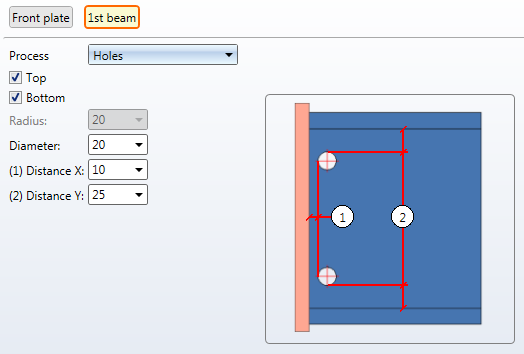
For integrating the web cuts, you determine the radius and the fitting position (top and/or bottom).
For installing the holes, you determine the installation position (top and/or bottom), the bore as well as the distance to the plate (1) and beam edge (2).
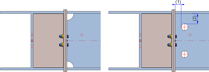
On the left: web cuts, on the right: holes
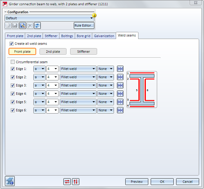
Here you can specify which weld seams are to be created for the front plate, the 2nd plate and the stiffener. You distinguish between weld seams for the front plate, the 2nd plate and the stiffeners.
For each edge you can select a type of thickness designation, a weld seam thickness, a weld seam type and an inspection category. If you want to use the same settings for the other edges, click the Equate  symbol.
For the Front plate and the 2nd plate, the seams for the two flange sides can be configured separately. The ISD default setting is Fillet weld, Thickness: a, Weld thickness: 4, Inspection category: None. If the weld seam type Double fillet weld is selected for one of the flange sides (Edge 1/2 or Edge 3/4), the other checkbox will be greyed out.
The weld seam type Double fillet weld is preset for stiffeners.

Connections + Variants (3-D SE) • Dialogue Window for Connections - Type II (3-D SE) • The Catalogue System for Connections + Variants (3-D SE)
|
© Copyright 1994-2018, ISD Software und Systeme GmbH |


 If you select the Inserted option here, the projections beyond the 2nd beam refer to the inner flange side.
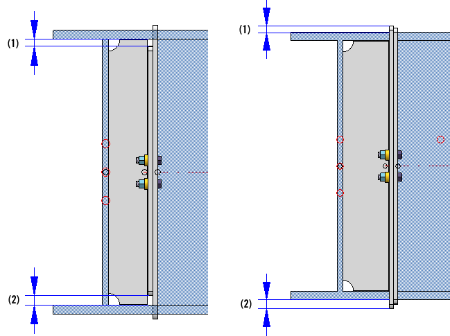
 Auto checkbox if you want HiCAD to automatically determine the width. In this case the width covering the area between the 2nd plate and the web will be automatically calculated (rounded to whole millimetres), taking the specified clearance into account.