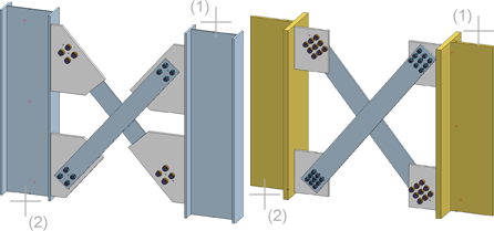
"Civil Engineering functions" docking window > Steel Engineering > Connections > Web/flange to Web/Flange > Cross-bracing (1601)
This Design Variant-based connection enables you to insert stabilizing cross-bracings between two existing columns.

After calling this function, HiCAD prompts you to identify the two vertical beams (columns) between which the bracing is to be fitted.
Please note the following:
The Cross-bracing dialogue window is displayed.
Configurations for cross-bracings can be saved, enabling you to access your individual, customised configurations at any time.
The following functions and information for configuration management are available:
|
|
Rename current configuration |
|
|
Save configuration |
|
|
Save configuration with a different name |
|
|
Delete configuration |
|
|
Reset input fields to the last saved state of the configuration |
|
|
Indicates that the current configuration has been changed, but not saved yet. |
To load a configuration, simply select it from the listbox.
To create a new configuration, simply load an already existing configuration, save it with a different name and change this copy according to your requirements.
 Use the Rule Editor to define customer-specific configurations, taking Steel Engineering-specific standards and construction guidelines (rules) into account. The operation of the Rule Editor requires programming skills and should therefore only be used by experienced programmers.
You use the different tabs of the dialogue window to configure the cross-bracing.
Selected parts
This tab is divided into two sub-tabs, 1st beam and 2nd beam, that provide information about the previously identified columns, such as beam type, material, dimensions etc. It is however not possible to make any entries here.
Standard Parts
In this area you specify the beams onto which the cross-bracing is to be mounted. Permissible types for the bracing are U- and L-beams and flat steels. Click the  icon to select the bracing member as well as the material directly from the corresponding Standard Part catalogues.
If there are any particular components that you do not want to be fitted, simply deactivate the corresponding checkbox.
Permitted beam and profile types are U- and L-beams and flat steels. Click the  symbol to select the beam/profile as well as the material directly from the corresponding standard part catalogues.
To select the desired bolting, click the  symbol and select the desired components in the Bolting dialogue window:
The selection of bolting components works in the same way as with the Boltings function in the 3-D module.
Plates
Use this tab to determine if you want to mount any plates to the bracing members, and, if so, to additionally specify the plate type. if you do not want a plate to be fitted, simply deactivate the corresponding checkbox.
For each 1st and 2nd plate of both bracing members you can specify the following settings:
 symbol to choose these data directly from the corresponding Standard Part catalogues.
|
|
|
|
Rectangular plate |
Pentagonal plate |
You can also copy the settings of the current tab to other plates. To do this, select the desired option from the Settings of this plate for... listbox at the top and click the Copy button.
Others
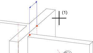
Here you can specify the distance from the beam axis. This value determines the fitting point of the first plate on the first identified column.

Click the Preview button if you want to display a preview of the connection based on the currently entered data. If you want to modify the current data, apply the required changes and click Preview again to update the preview. Click OK to insert the connection according to the current data and close the dialogue window. If you click the Cancel button, the window will be closed, and the specified or changed connection will not be inserted.
![]() Please note:
Please note:

Connections + Variants (3-D SE) • Dialogue Window for Connections -Type I (3-D SE) • The Catalogue System for Connections + Variants (3-D SE)
|
© Copyright 1994-2018, ISD Software und Systeme GmbH |