"Civil Engineering functions" docking window > Steel Engineering > Connections > Front side to web/flange side > Flange > Strap joint (1310)
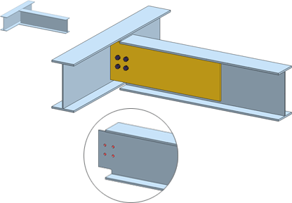
Use this function to connect two beams with a strap joint. This connection type consists of one or two bolted or welded straps and can be created with or without stiffeners. The beams to be connected need to be I-beams or U-beams.

Beams connected with strap joint - Connection type: Notch (top left: Original beams)
Identify the two beams that you want to connect. The dialogue window for strap joints is displayed.
Configurations for strap joints can be saved, enabling you to access your individual, customised configurations at any time.
The configuration of the strap joint takes place via the settings in the tabs of the dialogue window.
Selected parts
This tab provides information about the previously identified beams, e.g. designation, material, dimensions etc. Value inputs or modifications are not possible here.
Connection
On this tab you specify the settings for the plate.
|
Components/Option |
Input fields |
|---|---|
|
Connection type |
Specify how you want to connect the first identified beam:
|
|
Semi-finished product |
Click the symbol
|
|
Grid X/Y |
The bore grid determines the arrangement of the bores for the bolting.
|
Boltings
On this tab you specify the settings for the plate.

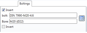
If you want the straps to be bolted to the beam, activate the Insert checkbox. Then specify the components of the bolting, e.g. the type of the bolt, bore diameter, etc. Click the  icon and select the individual components of the bolting. The selection is made in the same way as for the Steel Engineering Bolting function.
If you want to invert the direction of the bolting, activate the corresponding checkbox.
Stiffener
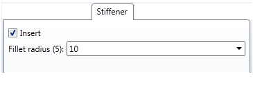
The strap joint can be fitted with or without stiffeners. Activate or deactivate the corresponding checkbox.

When inserting the stiffeners, you can also specify the fillet radius of the stiffener.
Notch
Depending on the fitting situation, the beam to be connected will be notched automatically. The corresponding settings can be specified in the Notch tab.
|
Type |
Bore out and Radius are available as notch types. Select the desired option and enter the fillet radius. |
|
Length, Height |
You can chose between automatic and manual input of length and height of the notch. Automatic determination selects the standardised minimum values for height and length according to DASt guidelines while taking the entered minimum flange distance into account. The following options are available:
|
Weld seams
In this tab you specify, by activating or deactivating the corresponding checkbox, whether the fitting will take place with or without weld seams. When inserting the weld seams you can also specify the thickness of the seam.
![]() Please note:
Please note:

Connections + Variants (3-D SE) • Dialogue Window for Connections (3-D SE) • The Catalogue System for Connections + Variants (3-D SE)
|
© Copyright 1994-2018, ISD Software und Systeme GmbH |