New in Sheet Metal 2012 (3-D SM)

Base Sheet
- New sheet from surface (SP1)
Use the New sheet from surface function to construct, via specification of a sheet thickness, new sheet metal parts from the surfaces of a 3-D body. Specify whether you want to apply the thickness to the inside, the outside or centrally. Double-clicking the corresponding Feature log entries enables you to modify the sheet subsequently. You can select an edge or a cylindrical surface as bend zone.
(1) Sheets (Facets)
(2) Bending edges
(3) Sheet metal part with relief groove
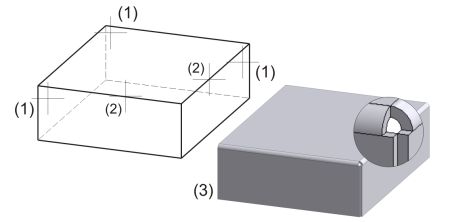
- New sheet from solid (SP1)
When creating a base sheet from a 3-D solid, you can now choose whether the sheet is to be generated with or without a bend zone.
(1) Solid
(2) Sheet with bend zone
(3) Sheet without bend zone
When creating base sheets, you can now load Semi-finished products data from the CATEditor, i.e. the Sheet thickness, the Bend radius, the Allowance method and the Material will be taken from the CATEditor.
Attach Flanges
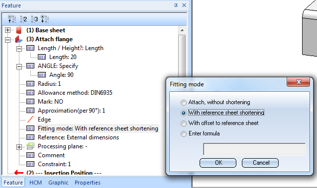
- Attach flange entry in Feature log (SP1)
You can now change the fitting mode via the Attach flange Feature log entry.
You can choose between the options Attach, without shortening, With reference sheet shortening and With offset to reference sheet.
- Attach Z-fold between 2 points
The new Attach Z-fold between 2 points function enables you to attach two contiguous sheets with relief groove creation.
Example
The Attach sketch function now also allows a mirroring of the sketch.
The flange will be fitted in negative X-direction according to the sketch. Right-click to switch the sketch to positive X-direction before identifying the connecting edge.
Example
Design Variant "Sheet Corner"
- A so-called Design Variant is an arbitrary number of variable design steps. Once created, the Design Variant can be re-used in other drawings, at any time and even by other users. If desired, Design Variants can also be modified and extended. Compared with invariable, pre-programmed joint functions, Design Variants are therefore much more flexible and suitable for a significantly wider field of application. The insertion of the Sheet corner Design Variant in Sheet Metal drawings takes place via the Civil Engineering functions docking window, by double-clicking the name of the variant or the preview image. Then, identify the edges for insertion. In the dialogue window you can adjust the parameters of the sheet corner for the sheet metal part.

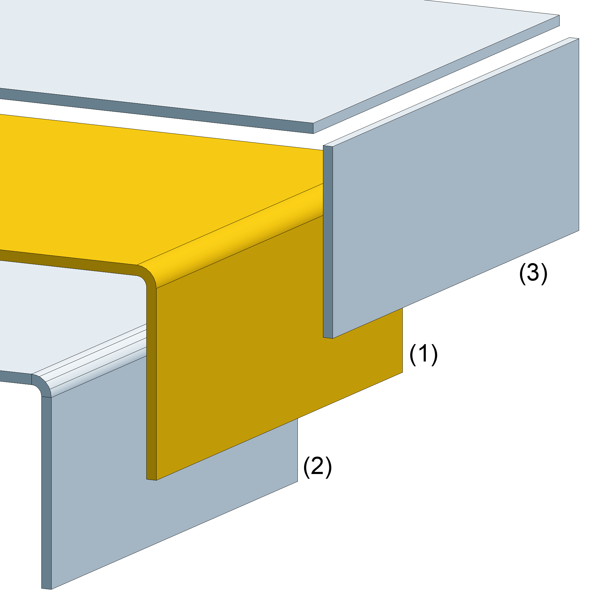
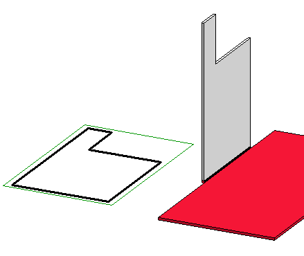
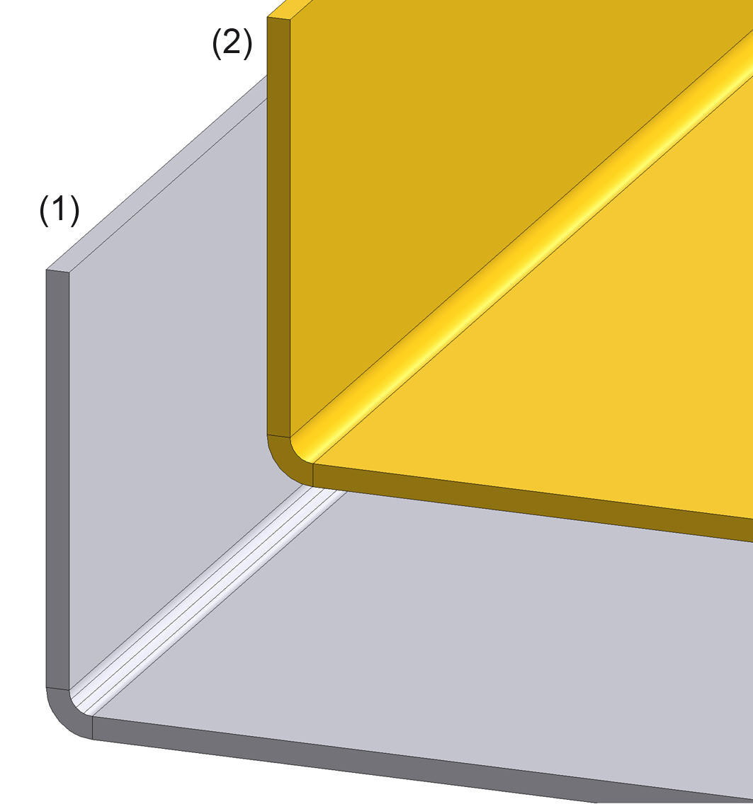
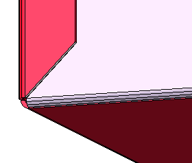
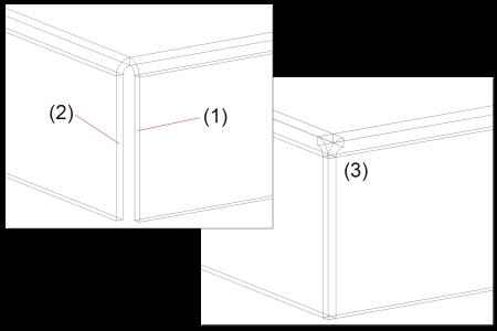
Close Corner, Outer Edge Flush
Use the new Close corner, Outer edge, flush function to lengthen each sheet to the outer edge of the other sheet. This also applies to the bend zone. (SP1)
- Identify the front edges of both sheets:
(1) Front edge
(2) Front edge
(3) Lengthened to outer edges of sheets (or shortened, if required)
Sheet Development
- To ensure an error-free processing, e.g. during laser cutting, the line elements must not be smaller than the laser beam. Before creating the development you can set a minimum line length. In this way it is ensured that, for example, the length of circular arcs will not fall below this minimum length during development.
You specify the minimum value in the CAM-relevant minimum length of development entry in the ABWPAR.DAT file in the HiCAD sub-directoy SYS. (SP2)
- In sheet developments, threads are now created as sub-parts, as in 2-D. This representation consists of a three-quarter circle. This applies to the new development and updated old developments. The modified structure will be taken into account for DXF export. (SP1)
Bend Zone Representation
In HICAD, bend zones can be displayed with or without segmentation. To display the , change the following entry in the SYS/ABWPAR.DAT file as shown below:
Cylindric representation of bend zones (yes/no=1/0)(without segmentation = 2) 2
Restart HiCAD for the changes to take effect. New bend zones will then be displayed with segmentation.
(1) with segmentation
(2) without segmentation
Mitre
- If the angle on a flange becomes too sharp, a neat closing of the corner is no longer possible. In such cases you can use the new Mitre, narrow side function that creates a stepped 45 ° mitre.
Example
Processing Direction
- You can now identify the Processing direction and processing side by means of a direction arrow. This enables you to perform the development from the side that has been identified by the arrow, and automatically align it horizontally to the direction symbol. This is also an advantage in case of DXF exports.
Solid from Sheet
When converting an itemized sheet to a solid, the item number and the BOM-relevance will be transferred. (SP2)
Powder Marking Lines
- The Powder marking lines function can now also be applied generally, and not just to Sheet Metal parts. As of Service Pack 2, the function can be accessed via 3-D Standard > Standard processings > Bore
 > Powder marking lines.
- In the Powder marking lines menu, the selection options for sheets to be projected have been extended, e.g. by the With selection of attached parts option.
Further Tools
- New moulding tools are available for semi-circular vents, trapezoidal vents, rectangular filleted vents, cup-shaped vents. If these are not displayed in the selection window for moulding tools, you need to activate them in the in the Catalogue Editor via the CATALOGUE MAKER. The moulding tools can be found at CATALOGUES > SHEET TOOLS. (SP2)
- The Lettering function can not only be applied to sheet metal parts, but to all 3-D parts. It has therefore be moved to the 3-D Standard tab. To access the function, select 3-D Standard > Standard Processing > Bore > Lettering).
Weld Seams
- If you use the 3-D function Weld seam (3-D Standard > Standard Parts) for a welding on of a sheet main part, the weld seams will be determined for all sub-parts, and superfluous (double) powder marking lines will be removed. If a sub-part is selected for a welding, only the sub-part will be welded on.
Bills of Materials
- When making a standard installation, sheet parts will be BOM-relevant and the BOM attributes will always be updated. You can change these standard settings in the ABWPAR.DAT file in the HiCAD SYS directory. (SP1)
- For sheet metal processing the special BOM configuration HICAD_Blech_01.RMS is now available.
Related Topics
HiCAD Sheet Metal • General Notes on Sheet Metal Processing • Overview of Functions • News 2010
Version 1702 - HiCAD Sheet Metal | Date: 9/2012 | © Copyright 2012,
ISD Software und Systeme GmbH
 Example