 Please note:
Sheet Metal > Sheet development > Develop sheet
The Develop sheet pull-down menu in the Sheet development function group provides various functions for developing (=cutting to size) a folded sheet part or any 3-D part. The result is a 2-D development or a so-called blank.
The Develop sheet function can also be accessed by right-clicking a sheet metal part and selecting the function from the context menu.
To define the representation , click the Settings icon, then select Settings > Basic settings > Sheet Metal Development > General. You can also choose whether you want the 2-D blank to be available globally or assigned to the active sheet.
Please note:
To ensure an error-free processing, e.g. during laser cutting, the line elements must not be smaller than the laser beam. Before creating the development you can set a minimum line length. In this way it is ensured that, for example, the length of circular arcs will not fall below this minimum length during development.
You specify the minimum value in the CAM-relevant minimum length of development entry in the ABWPAR.DAT file in the HiCAD sub-directoy SYS.
| Functions | Description | |
|---|---|---|
|
|
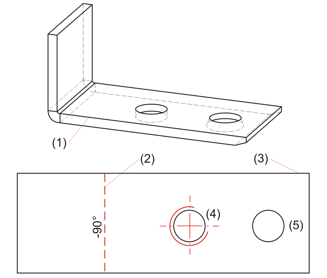
This function generates the development of a sheet part without displaying the hidden edges. Identify an edge of the basic sheet. The development then attaches to the cursor and can be freely positioned in the drawing. |
|
Pull-down menu  Dev. Dev. |
||
|
|
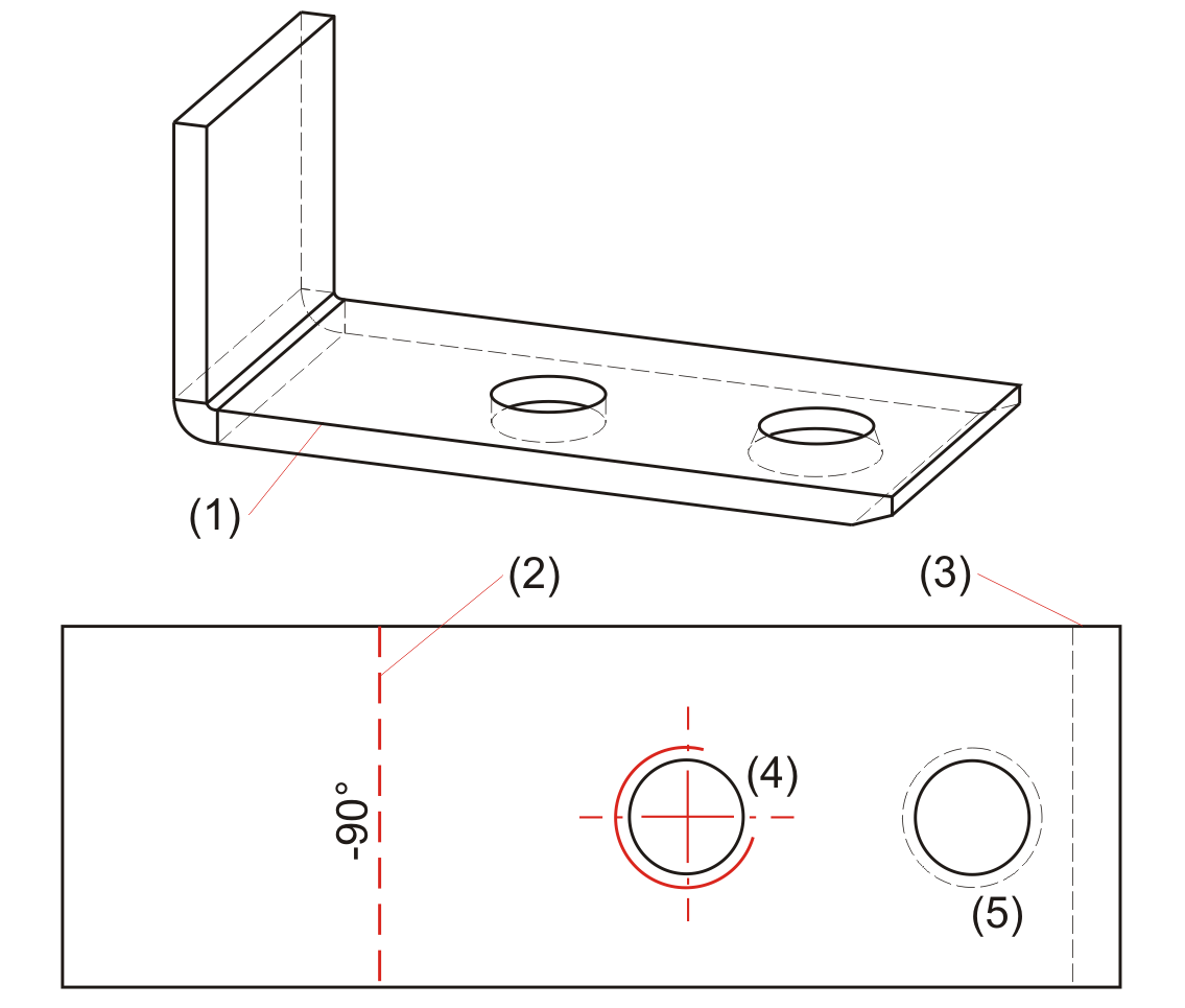
This function generates the development of a sheet part. The hidden edges are displayed dashed. Identify an edge of the basic sheet. The development then attaches to the cursor and can be freely positioned in the drawing. |
|
|
|
You use this function to develop the lateral surface of a 3-D part, taking into account the connecting angle In other words, all surfaces that do not exceed the connecting angle are taken into account.
|
|
|
|
You use this function to develop the lateral surface of a 3-D part and its sub-parts, taking into account the connecting angle. In other words, all surfaces that do not exceed the connecting angle are taken into account. The sub-part must be added to the main part below the connecting angle.
|
|
|
|
Use this function to develop the outer shell of a 3-D part (e.g. a truncated cone) analytically. You are always prompted to specify an offset (sheet thickness) for the cutting depth. For filleted surfaces, this will cause changes of the surface area of the developed object.
When developing freeform surfaces, the sheet thickness always need to be set to 0, and automatic sheet thickness detection (RMB) must not be started!
For freeform surfaces: 0.
The tear-open point determines the cutting line in the lateral surface.
|
|
|
|
Use this function to start automatic sheet thickness calculation immediately after identification of the surface of a 3-D part (solid, freeform surface). After calculation of the surface thickness, the offset will be set, without any further entries, to half of the sheet thickness, i.e. the development takes place on the neutral axis. If the sheet thickness cannot be calculated, an input window appears. For freeform surfaces you always need to set the sheet thickness to 0.
The tear-open point determines the cutting line in the lateral surface.
|
|
![]()
Related Topics
Function Overview • General Information on Sheet Processing • Blank Parameters
Version 1702 - HiCAD Sheet Metal | Date: 9/2012 | © Copyright 2012, ISD Software und Systeme GmbH
 Example


 Please note: