 > Powder marking lines
3-D Standard > Standard Processings > Bore > Powder marking lines
Use this function to manually or automatically project so-called powder marking lines onto the outer surfaces of the active/selected part. Powder marking lines are caused by the outer surfaces of parts lying within the outer surface of the active/selected part (taking certain tolerance values into account). In this way you can, for example, highlight the contours of parts which are to be welded together.
The powder marking lines are included for sheet developments, and are also considered for DXF exports, with the specified parameters. The functionalities of the DSTV-NC powder marking line generation are supported as well.
Distance tolerance: Considers only surfaces whose distance to the (parallel) outer surface of the active/selected part is smaller than the specified value.
Angle tolerance: Considers only surfaces whose angle to the (parallel) outer surface of the active/selected part is smaller than the specified value.
Minimum length: Edges which are shorter than the specified minimum length will not be considered for powder marking line search.
The powder marking lines will be detected and displayed on the assembly main part. Update the 2-D development to apply the powder marking lines.
For each powder marking line search, a feature called Powder marking lines will be created for the feature log of the part onto which the lines have been projected. If you have selected the Part with attached part mode, such an entry will be created for each identified attached part (provided that any powder marking lines exist).
If no powder marking lines could be found, the message No powder marking lines created. will be displayed.
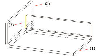
(1) Sheet metal main part
(2) Sheet metal flange
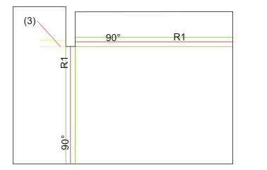
(3) Powder marking line

Related Topics
Version 1702 - HiCAD Sheet Metal | Date: 9/2012 | © Copyright 2012, ISD Software und Systeme GmbH